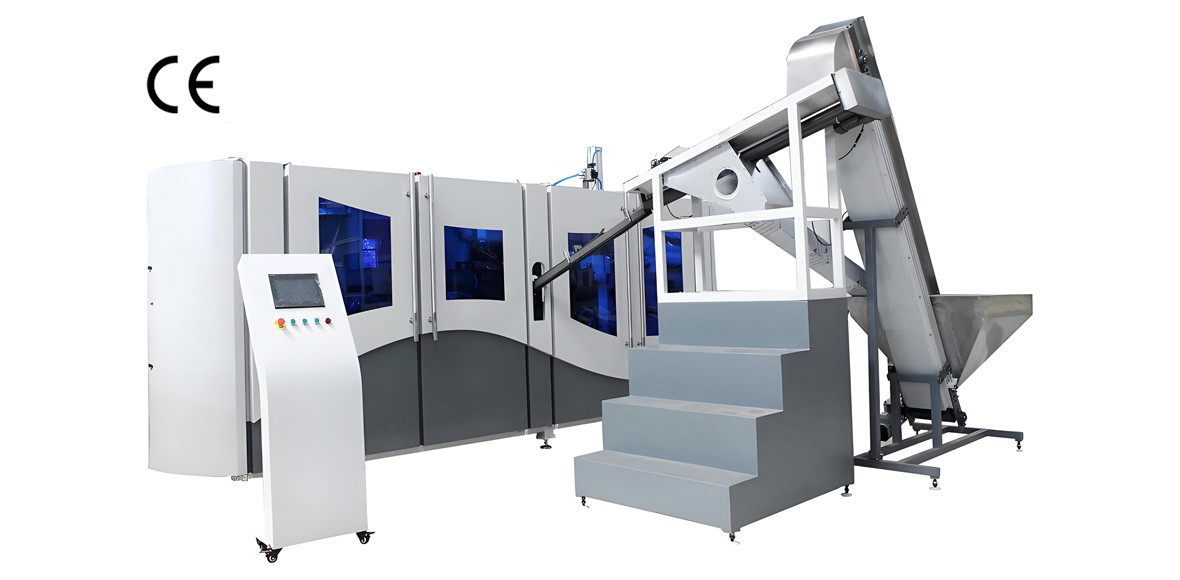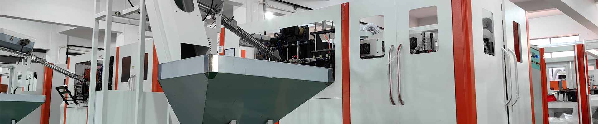
Improving the finished product rate of PET flat blow molding bottle production is the single highest-leverage action available to most bottle plants, because resin and preform cost dominate the conversion economics and every scrapped bottle throws away material that has already been paid for twice, once as resin and once as the electricity used to reheat it. PET flat blow molding is the ambient-temperature, non heat-set two-step stretch blow molding route used for cold-filled products such as drinking water, carbonated soft drinks, juice, edible oil and household chemical liquids, in contrast to heat-set blowing where the mold runs hot and the bottle is crystallized in the cavity to survive hot filling. Because the flat blow molding process runs chilled molds and relies almost entirely on strain-induced biaxial orientation for its strength, it is extremely sensitive to preform condition, oven temperature profile and pre-blow timing. A line that drifts by a few degrees Celsius in the body heating zone can move from 99 percent first-pass yield to 94 percent within a single shift, and nobody notices until the palletizer starts rejecting.
YuDa, a Wanplas factory, has spent more than twenty years building PET bottle blow molding machines for customers in over sixty countries, holds more than twenty patents, and is recognized as a top two manufacturer of PET bottle blow machines in China. That experience is grounded in a simple observation repeated across hundreds of installations: the machine sets the ceiling for achievable yield, but daily discipline in preform handling, oven profiling and process monitoring decides where a plant actually operates under that ceiling. This guide is written for production managers, process engineers and quality supervisors who need to move a line from acceptable to excellent. It sets out how to define and measure finished product rate honestly, maps thirteen common defects to their root causes and countermeasures, specifies incoming preform acceptance criteria, defines the heating and blowing parameter windows that keep the process centered, explains how to build process capability data that actually predicts scrap, and closes with the machine platforms, selection logic and support structure that make consistent yield achievable rather than accidental.
Throughout the article, numbers are given as practical working ranges observed across typical flat blow molding applications. Every bottle design behaves slightly differently, and a plant should treat published ranges as starting points to be confirmed during trial molding, not as universal constants. The discipline that separates high-yield plants from average ones is not access to secret parameters; it is the habit of recording what worked, freezing it as a recipe, and detecting drift before it becomes scrap.
What Finished Product Rate Actually Measures
Finished product rate only becomes a useful management tool once the plant agrees on exactly what counts as a good bottle, where the count is taken, and what happens to bottles that are reworked or re-inspected. Plants that report 99 percent while filling lines complain about leakers are almost always counting at the wrong point or quietly excluding categories of loss.
First-Pass Yield, Rework Rate and Final Yield
Three distinct numbers describe the same production run, and confusing them is the most common measurement error in bottle plants. First-pass yield is the proportion of bottles that leave the blower and pass every inspection without any intervention. Rework rate covers bottles pulled out for re-inspection, manual sorting or re-blowing of the same preform batch. Final yield is the proportion of bottles that ultimately ship or reach the filler. A plant can post a respectable final yield while burning enormous hidden cost in sorting labor, so first-pass yield is the metric that should drive engineering attention.
The counting boundary matters just as much. Best practice is to count at the blower discharge conveyor, before the air conveyor and before any downstream buffer, using a preform-in versus bottle-out reconciliation each shift. Preforms consumed minus good bottles counted equals total loss, and that total must then be broken down by category. If the two counts never reconcile, the plant has an unmeasured loss channel, usually startup purge bottles or bottles removed by operators without being logged.
| Metric | Definition | Measurement point | Typical mature line | Typical ramp-up line |
|---|---|---|---|---|
| First-pass yield | Bottles passing all checks with no intervention, divided by preforms fed | Blower discharge conveyor | 98.5 to 99.5 percent | 92 to 96 percent |
| Startup and changeover loss | Purge bottles produced while the oven stabilizes after start or mold change | Counted separately per event | 150 to 400 bottles per start | 400 to 1200 bottles per start |
| Rework and sort rate | Bottles requiring manual inspection or re-sorting before release | Sorting station | Below 0.3 percent | 1 to 3 percent |
| Final yield | Bottles accepted by the filling line or warehouse | Filler infeed or palletizer | 99.0 to 99.7 percent | 95 to 98 percent |
| Customer complaint rate | Bottles rejected after delivery, expressed per million | Customer inspection report | Below 200 per million | 500 to 3000 per million |
| Preform to bottle reconciliation gap | Unexplained difference between preforms consumed and bottles accounted for | Shift material balance | Below 0.1 percent | 0.5 to 2 percent |
Defect Classification: Appearance, Dimensional and Functional
Every scrap bottle should fall into exactly one of three categories, because the three categories have entirely different root cause families and entirely different economic consequences. Appearance defects such as pearlescence, heat marks, gate blush and haze are usually heating or timing problems, and they are visible on the line. Dimensional defects such as volume deviation, height variation, body diameter drift and out-of-round necks are usually preform, mold or clamping problems, and they only surface through measurement. Functional defects such as leakage, base stress cracking, top load failure and thread incompleteness are the most dangerous class because they can pass visual inspection and fail at the customer.
Sorting scrap into these three buckets on a daily Pareto chart changes the conversation in the morning meeting. Instead of a single scrap percentage that nobody can act on, the team sees that 62 percent of the loss is appearance-related and concentrated on two cavities, which immediately points at lamp zoning or a specific mold half rather than a vague material complaint.
Sampling Plans and Acceptance Criteria
Continuous 100 percent automatic inspection of every bottle is not economically justified for most flat blow molding operations, so the plant relies on a structured sampling plan supplemented by inline leak detection where the product demands it. A workable sampling structure for a line running one product family is a small dimensional sample every hour, a full-cavity sample at every startup and every parameter change, and a destructive test sample once per shift. Each cavity must be identifiable, either by an engraved cavity number on the bottle base or by a fixed discharge sequence, because cavity-level traceability is what turns a scrap number into a corrective action.
| Check | Frequency | Sample size | Acceptance criterion | Action on failure |
|---|---|---|---|---|
| Bottle weight | Every hour | One bottle per cavity | Within plus or minus 1.0 percent of nominal | Check preform lot and oven output; hold last hour of production |
| Overall height and body diameter | Every 2 hours | One bottle per cavity | Within drawing tolerance, normally plus or minus 0.5 mm | Check mold closing, base mold stroke, cooling water temperature |
| Brim-full volume | Every 4 hours | 3 bottles per cavity | Within plus or minus 1.5 percent of nominal | Verify preform weight and pre-blow timing |
| Wall thickness distribution | Every shift | 2 bottles per cavity, sectioned | Minimum wall above design floor, no zone below 0.12 mm on light bottles | Re-profile oven lamp distribution |
| Top load and perpendicularity | Every shift | 5 bottles per cavity | Above product specification, tilt below 1.5 mm | Review stretch ratio and base mold temperature |
| Burst pressure, carbonated bottles | Every shift | 3 bottles per cavity | Meets product specification, commonly at or above 1.0 MPa depending on bottle design | Stop and investigate before release |
| Drop test | Daily | 5 bottles filled | No leakage or base failure at specified drop height | Investigate base material distribution |
| Leak test | Continuous or per pallet | Per line capability | Zero leakers released | Quarantine pallet, 100 percent sort |
| Full first-article check | Every startup and changeover | All cavities, complete dimension set | All CTQ dimensions in tolerance | Do not release production until passed |
The PET Flat Blow Molding Defect Atlas
Almost all scrap in flat blow molding traces back to a short list of recurring defects, and each one has a characteristic signature that a trained operator can read directly off the bottle. The atlas below is the working reference that should sit laminated at the machine. Note that several defects share root causes: insufficient preheat produces both pearlescence and poor material distribution, and excessive preheat produces both heat marks and neck deformation, which is exactly why blind parameter changes so often trade one defect for another.
| Defect | Visible symptom | Primary root causes | Countermeasure sequence |
|---|---|---|---|
| Pearlescence, stress whitening | Milky, silvery sheen on shoulder or body, loss of gloss | Insufficient preheat, excessive stretch ratio, pre-blow too early, cold preforms from storage | Raise body zone lamp power in 2 to 3 percent steps; delay pre-blow onset by 5 to 15 ms; condition preforms to workshop temperature; verify oven residence time |
| Gate blush, base whitening | White or hazy halo around the injection gate on the bottle base | Gate zone underheated, stretch rod speed too high, stretch rod not centered, base mold too cold | Increase gate zone lamp output; reduce stretch rod acceleration; center and align the rod; raise base mold water temperature toward the upper half of the range |
| Uneven wall thickness, eccentricity | One side thin and one side thick; section weights differ across quadrants | Preform rotation stalling in the oven, lamp reflector fouling, preform wall eccentricity from injection, uneven cooling of the neck | Verify every mandrel rotates; clean reflectors and lamps; measure preform eccentricity; check spindle drive belt tension |
| Heat marks, lamp stripes | Horizontal banded stripes or ripples on the body corresponding to lamp positions | Preform surface overheated locally, preform too close to lamps, insufficient rotation, cooling plate malfunction | Lower the affected zone power; increase distance or restore the cooling plate airflow; confirm rotation speed; balance neighboring zones |
| Neck deformation, oval finish | Thread area distorted, finish out of round, cap application torque erratic | Neck support cooling insufficient, oven heat radiating above the neck shield, low neck crystallinity in the preform, overheated transfer | Restore neck cooling water flow; adjust the neck shield gap; verify the preform supplier neck crystallinity; reduce the top zone lamp output |
| Base stress cracking | Fine radial cracks in the base after filling or during storage, especially carbonated | Thick unoriented material at the gate, residual stress, base mold temperature too high, poor petaloid material distribution | Increase gate area preheat slightly; hold base mold at 8 to 12 degrees Celsius; re-balance the stretch and pre-blow relationship; verify preform gate quality |
| Volume out of tolerance | Brim-full volume above or below specification | Preform weight drift, oven temperature drift, pre-blow pressure change, incomplete mold closing | Weigh incoming preforms; recheck oven set values against recipe; verify pre-blow pressure regulator; inspect clamping |
| Body paneling, vacuum collapse | Bottle sidewalls suck inward after filling and cooling | Wall too thin in the panel area, insufficient orientation, inadequate vacuum panel design, hot product filled into ambient bottle | Redistribute material toward the panel zone; raise the axial stretch ratio slightly; review bottle design with the mold shop |
| Poor clarity, high haze | Cloudy body, low light transmittance, poor shelf appearance | Excess acetaldehyde or moisture in the preform, over-crystallized preform, degraded resin, contaminated regrind in the preform | Verify preform incoming quality; check preform storage and yellowing; reject the affected preform lot; confirm bottle-grade PET resin specification |
| Flash at the parting line | Thin fin of material along the mold split or base insert | Insufficient clamping force, worn parting faces, foreign matter on the sealing surface, blow pressure too high | Verify clamping pressure and toggle wear; clean and stone the parting faces; reduce high pressure blow if excessive |
| Bottle tilt, poor perpendicularity | Bottle leans when placed on a flat surface, unstable on the conveyor | Asymmetric material distribution, base mold not seated, uneven cooling, stretch rod off center | Section-weigh quadrants; verify base mold elevation and seating; re-center the rod; even out the lamp zones circumferentially |
| Incomplete thread, short finish | Thread crest not fully formed, cap does not seal reliably | Preform neck damage, worn neck support, mold not fully closed, transfer misalignment | Inspect the incoming preform finish; replace the neck support tooling; verify mold closing sequence |
| Leakage at the cap seal | Filled bottle leaks at the closure under pressure or inversion | Deformed sealing surface, contamination on the finish, out-of-round neck, damaged top sealing land | Check the neck cooling and the shield; inspect the finish for scuffing during transfer; verify the closure specification match |
Pearlescence and the Stretch Limit
Pearlescence is not a cosmetic curiosity; it is a direct signal that the material has been pushed past its natural stretch ratio at the temperature it was given. PET orients well between roughly 95 and 115 degrees Celsius, and within that band the polymer chains align without voiding. Below the band the material behaves more like a rigid solid, micro-voids nucleate as it is forced to deform, and those voids scatter light. Because the effect appears first where the material is coldest and thinnest, pearlescence typically shows on the shoulder transition or on the lower body just above the base.
The correct diagnostic sequence is to determine whether the whitening is uniform around the circumference or localized. Uniform whitening points to a global preheat deficit, meaning the oven set values, the chain speed or the preform conditioning are wrong. Localized whitening on one side points to rotation failure on individual mandrels or to reflector fouling in one zone. Localized whitening in the same position on every bottle from a single cavity points at that cavity’s mold cooling or at a blocked vent.
Gate Blush and the Base Region
The bottle base is the hardest region to get right in flat blow molding because it must be simultaneously thick enough to resist internal pressure and well oriented enough to resist stress cracking. The injection gate leaves a small mass of material that is difficult to heat evenly and that arrives at the mold last. Gate blush appears when this mass is stretched while too cold, and it is aggravated by an over-aggressive stretch rod that punches through before the material is ready.
Practical control comes from three levers used together. First, dedicate the lowest oven zone to gate heating and treat it as an independent variable rather than a follower of the body zones. Second, tune stretch rod speed so the rod leads the material rather than dragging it, typically arriving at the base a few milliseconds before pre-blow. Third, control the base mold temperature separately from the body mold. Base mold water that runs too warm delays freezing and encourages crystalline haze; water that runs too cold freezes the gate area before it can orient.
Wall Thickness Distribution and Heat Marks
Wall thickness distribution is the master variable behind top load, burst pressure, drop resistance and paneling, and it is entirely determined by the temperature profile written into the preform in the oven. A useful mental model is that the oven does not heat a preform, it writes a program into it: each vertical zone stores a specified amount of energy, and during blowing the hotter zones expand first and thin out most. Getting distribution right therefore means shaping the vertical energy profile deliberately rather than simply making the preform hot enough to blow.
Heat marks are the failure mode at the other end of the same axis. When a zone receives more radiant energy than the preform surface can conduct inward during rotation, the surface layer overheats while the core stays cool. That produces banded stripes, a rough surface texture and sometimes localized thinning. The fix is usually a combination of reducing that zone, increasing the cooling plate airflow across the preform surface and confirming that rotation speed is high enough that no facet of the preform lingers in front of a lamp.
Neck Deformation, Base Cracking and Leakage
Functional defects clustered around the finish and the base share one characteristic: they usually pass visual inspection at the blower and fail later at the filler or at the customer. Neck deformation is caused by heat migrating above the neck support shield, by loss of neck cooling water flow, or by a preform whose neck crystallinity was inadequate to begin with. Because the finish is molded during preform injection and must survive the blowing process unchanged, any heat reaching it is pure loss.
Base stress cracking deserves particular respect on carbonated applications because it typically appears days after production, when the bottle is already in distribution. The mechanism combines residual stress from poorly oriented base material with the sustained hoop stress of carbonation and, frequently, contact with caustic cleaning residues. Prevention is entirely upstream: correct gate heating, controlled stretch rod contact, base mold temperature in the lower half of the recommended range, and a base design that spreads material evenly through the standing ring. Any plant producing carbonated bottles should run periodic stress crack resistance testing rather than relying on burst pressure alone.
Incoming Preform Control: Where Most Yield Is Won or Lost
In a two-step flat blow molding operation the preform is the product; the blower merely reshapes it. Plants that chase yield exclusively through machine parameters while accepting whatever preforms arrive on the truck are optimizing the smaller half of the equation. Experience across many installations suggests that somewhere between one third and one half of chronic yield loss on a stable line originates in preform variation rather than in blower settings.
Intrinsic Viscosity, Moisture and Acetaldehyde
Bottle-grade PET resin for flat blow molding normally sits between 0.76 and 0.84 dL/g intrinsic viscosity. The lower end suits lightweight still water bottles where stretch is moderate and cost per bottle dominates; the upper end suits carbonated soft drinks, larger edible oil containers and any bottle where melt strength during preform injection and stress crack resistance in service matter more than a fraction of a gram. Mixing IV grades within a single production run is a reliable way to destroy yield, because the two populations require different oven profiles and the blower cannot tell them apart.
Moisture control belongs to the preform injection stage but its consequences arrive at the blower. Resin must be dried to below 50 ppm moisture, which in practice means a dehumidifying dryer holding roughly minus 40 degrees Celsius dew point with adequate residence time at the specified drying temperature. Inadequate drying causes hydrolytic chain scission during plasticizing, lowering effective IV, raising acetaldehyde and producing preforms that look normal but blow into hazy, brittle bottles. Acetaldehyde content matters for still water in particular, because the taste threshold is low and a bottle that is dimensionally perfect can still be rejected on sensory grounds.
At the blowing stage, the moisture risk changes character. Bulk moisture reabsorbed by a stored preform has limited effect on blowing, but surface condensation has a large effect. A pallet of preforms brought from a cold warehouse into a humid workshop will sweat, and wet preforms entering the oven absorb radiant energy unevenly and arrive at the mold with an unpredictable temperature profile. This is one of the most common causes of unexplained morning-shift scrap in tropical climates.
Preform Weight Tolerance, Neck Geometry and Crystallinity
Preform weight tolerance of plus or minus 0.5 percent is the practical target for a supplier serving a high-yield flat blow molding line. Every gram of variation translates directly into wall thickness variation in the finished bottle, and because the oven delivers energy on a time basis rather than a mass basis, a heavier preform arrives colder and a lighter preform arrives hotter at identical settings. On a lightweight 500 ml water bottle a 1 percent weight swing can be the difference between a clean bottle and pearlescence.
The neck finish must arrive undamaged and adequately crystallized. Neck crystallization gives the finish the thermal stability it needs to survive the oven without deforming, and its typical appearance is the familiar opaque white band. Preforms with inconsistent or partial neck crystallization deform unpredictably under the neck shield, producing out-of-round finishes that then leak at the closure. Support ring flatness and diameter also matter, since the ring carries the preform through the entire transfer chain and any burr or deformation causes transfer misalignment.
| Parameter | Target or limit | Test method | Frequency | Consequence if out of specification |
|---|---|---|---|---|
| Intrinsic viscosity | 0.76 to 0.84 dL/g, single grade per run | Solution viscosity, supplier certificate plus periodic verification | Every lot certificate, verification quarterly | Inconsistent stretch behavior, haze, stress cracking |
| Residual moisture of resin before injection | Below 50 ppm, dew point around minus 40 degrees Celsius | Supplier process record | Every lot | Chain scission, haze, brittle base |
| Acetaldehyde content | Low, per water or beverage brand specification | Headspace analysis at supplier | Every lot for water applications | Sensory rejection by the filler |
| Preform weight | Nominal plus or minus 0.5 percent | Precision balance, 20 pieces per box sample | Every pallet | Wall thickness and volume variation |
| Preform total length | Drawing tolerance, commonly plus or minus 0.3 mm | Height gauge | Every lot | Oven position mismatch, base defects |
| Wall eccentricity | Below 5 percent of nominal wall | Sectioning and micrometer, or wall scanner | Every lot | One-sided thin wall, bottle tilt |
| Neck finish dimensions | Per finish standard drawing | Go and no-go gauges, projector | Every lot | Cap leakage, application torque failure |
| Neck crystallinity band | Uniform, complete, correct height | Visual against boundary sample | Every pallet | Neck deformation in the oven |
| Support ring flatness and burr | No burr, flat within drawing | Visual and gauge | Every pallet | Transfer misalignment, dropped preforms |
| Gate quality | Flush, no crystalline ring, no stringing | Visual against boundary sample | Every pallet | Gate blush, base cracking |
| Color and clarity | Within color boundary samples, no yellowing | Visual, optionally colorimetric | Every lot | Haze, customer rejection |
| Contamination, black specks | Zero visible specks in the body wall | Backlit visual inspection | Every pallet | Appearance rejection, weak point in the wall |
| Storage conditioning time | 24 to 48 hours after injection before blowing | Lot date tracking | Every lot | Dimensional drift, unstable neck |
| Storage environment | 15 to 30 degrees Celsius, relative humidity below 65 percent, sealed bags | Warehouse log | Continuous | Surface condensation, dust contamination |
Storage, Conditioning and the 24 to 48 Hour Rule
Freshly injected preforms continue to change for a period after molding. Residual heat dissipates, dimensions relax slightly and the neck finish stabilizes. Blowing preforms that are only a few hours old produces measurably different results from blowing the same preforms two days later, which is why most disciplined plants apply a conditioning window of 24 to 48 hours between injection and blowing. Where preform injection and blowing sit in the same facility, this rule is easy to break under production pressure and should be enforced through the warehouse system rather than through operator judgment.
Storage conditions themselves are a genuine process parameter. Preforms should be kept in sealed bags or covered octabins, between roughly 15 and 30 degrees Celsius, at relative humidity below 65 percent, away from direct sunlight and away from doorways where temperature swings. In cold climates, incoming pallets must be allowed to equilibrate to workshop temperature before the bags are opened, otherwise condensation forms on the cold preform surfaces the moment they meet workshop air. In hot and humid climates the opposite discipline applies: keep the bags closed until the preforms are needed so the material does not sit absorbing ambient moisture and dust.
Incoming Visual Inspection Checklist
A short, rigorously executed visual inspection at goods receipt catches the majority of preform problems before they become a production stoppage. The checklist should be a single page that a warehouse operator can complete in a few minutes per pallet: bag integrity and labeling; lot number and injection date; visible yellowing against a boundary sample; black specks or foreign matter under backlight; gate appearance including crystalline rings and stringing; neck crystallization band uniformity; support ring burrs; deformed or flattened preforms from stacking pressure; and a twenty-piece weight sample. Any pallet failing two or more items should be quarantined pending engineering review rather than run in the hope that the blower can compensate.
The Heating Window: Oven Physics and Lamp Power Distribution
The reheat oven is where finished product rate is decided, because everything the blow station does afterwards is constrained by the temperature profile the oven wrote into the preform. Most flat blow molding applications work with an average preform body temperature between 95 and 115 degrees Celsius as it leaves the oven, with the exact target depending on preform weight, wall thickness, bottle stretch ratio and line speed.
Vertical Zoning and Lamp Power Distribution
The oven is divided into vertical zones, each served by a bank of infrared lamps whose output is set as a percentage. The distribution across those zones, not the average temperature, is what determines material distribution in the bottle. A useful starting logic is that the neck-adjacent top zone runs low to protect the finish, the upper body zones run moderate, the main body zones carry the highest output because that region must stretch the most, and the lowest zone dedicated to the gate area runs elevated to prevent gate blush.
Adjusting the profile should always be done one zone at a time, in increments of two to three percent, with at least the full oven residence time allowed before judging the effect. Operators who change three zones at once and immediately look at the next bottle are guaranteeing that they will never learn which change did what. The single most valuable habit a plant can install is the rule that only one process variable changes at a time and that every change is logged with the resulting section weights.
| Parameter | Typical working range | Effect if too low | Effect if too high | Control note |
|---|---|---|---|---|
| Preform body temperature at oven exit | 95 to 115 degrees Celsius | Pearlescence, high pressure required, poor material distribution | Heat marks, neck deformation, base haze, bottle shrinkage | Measure with a calibrated infrared pyrometer at a fixed point and fixed distance |
| Top zone, neck adjacent | Low, commonly 20 to 45 percent of maximum | Cold shoulder, thick unstretched shoulder ring | Neck deformation, oval finish, cap leakage | Verify neck shield gap and cooling water before raising |
| Upper body zones | Moderate, commonly 55 to 80 percent | Thick shoulder, thin lower body | Thin shoulder, panel weakness | Adjust with shoulder section weight as feedback |
| Main body zones | High, commonly 70 to 95 percent | Pearlescence, high burst pressure requirement | Heat marks, excessive thinning, paneling | Largest single influence on body wall |
| Gate zone, lowest | Elevated, commonly 65 to 90 percent | Gate blush, base stress cracking | Base haze, crystallized gate, thick base | Treat as an independent variable, not a follower |
| Preform rotation speed | Sufficient that no facet dwells in front of a lamp | Circumferential temperature bands, one-sided thinning | Rarely harmful, mechanical wear increases | Verify every mandrel physically rotates each shift |
| Chain pitch and heater distance | Machine design value, tighter pitch improves efficiency | Longer oven needed for the same energy | Adjacent preform shadowing | YuDa minimizes heater distance to 38.1 mm on its ovens |
| Oven residence time | Set by chain speed and oven length | Surface hot and core cold, unstable blowing | Cycle time penalty, over-conditioning | Balance against equalization time before the blow station |
| Cooling plate airflow | Continuous, unobstructed | Surface overheating, heat marks | Excessive surface chilling, higher lamp demand | Clean filters weekly, verify fan operation |
| Workshop ambient temperature | Stable, ideally 18 to 30 degrees Celsius | Preforms enter cold, whitening in winter | Preforms enter warm, over-heating in summer | Apply seasonal recipe offsets rather than ad hoc tweaks |
| Workshop relative humidity | Below 65 percent | Static and dust pickup | Surface condensation on cool preforms | Condition preforms before unbagging |
Rotation Uniformity and Chain Pitch
Every preform must rotate continuously and at a consistent speed through the entire oven. A single mandrel whose rotation has stalled because of a worn bearing, a slipping belt or accumulated debris will produce a bottle with a hot stripe and a cold stripe, which typically shows as a one-sided thin wall and a bottle that tilts. Because this defect appears on only one bottle in every full carousel rotation, it can hide inside an apparently modest scrap percentage for weeks. A thirty-second visual check of mandrel rotation at every shift start is one of the highest-return inspections in the plant.
Chain pitch, the spacing between adjacent preforms on the oven chain, and heater distance, the gap between the lamps and the preform surface, together determine how efficiently radiant energy reaches the material. Tighter heater spacing places more of the emitted energy on the preform rather than on the oven walls. YuDa machines minimize the heater distance to 38.1 mm, which reduces the energy required to reach the same preform temperature and, more importantly for yield, produces a steeper and more controllable vertical profile because each lamp bank influences a better-defined band of the preform.
Ambient Conditions and Seasonal Compensation
Reheat ovens are open thermal systems, so workshop conditions are part of the process. A plant that runs the same recipe in January and July will produce different bottles, because the preform enters the oven at a different starting temperature and the cooling plate air is at a different temperature and humidity. The professional response is not to forbid parameter changes but to formalize them: maintain a base recipe and a documented set of seasonal offsets, so that the summer profile and the winter profile are both engineered states rather than the accumulated residue of operator adjustments.
Air conditioning or at least ventilation control in the preform staging area pays for itself in reduced startup scrap. So does a simple rule that preform pallets must sit in the workshop for a defined period before use. Where a plant experiences a consistent yield gap between the first hour of a shift and the rest of the day, ambient conditioning is almost always the explanation.
Stretch Blow Molding Parameters and the Pre-Blow Timing Window
Once the oven has written a temperature profile into the preform, the blow station has a few tens of milliseconds to convert it into a bottle. Within that window, the relationship between stretch rod motion and pre-blow air is the dominant determinant of material distribution, and the sequence matters far more than the absolute pressures.
Stretch Rod Motion and the Pre-Blow Window
The stretch rod’s job is to establish axial orientation and to hold the preform base centered while the pre-blow air begins radial expansion. If pre-blow arrives too early, the material balloons before the rod has stretched it axially, producing a thin shoulder, a thick base and often pearlescence in the transition. If pre-blow arrives too late, the rod drags cold material down, pushing the gate mass into the base and inviting gate blush and stress cracking. The correct setting is the point where the expanding bubble follows just behind the rod tip.
Pre-blow pressure in flat blow molding typically runs between 0.6 and 1.2 MPa. Lower pressure gives a gentler, later expansion suited to lightweight bottles; higher pressure suits heavier preforms and bottles with aggressive shoulder geometry. High pressure blow, which forces the material into the final cavity detail, generally runs between 2.5 and 4.0 MPa, with carbonated bottle applications and complex base geometries sitting in the upper half of the range. Exhaust delay determines how long the bottle is held against the chilled cavity before the air is released and directly influences shrinkage and dimensional stability.
| Parameter | Typical range | Increase it when | Decrease it when | Yield risk if wrong |
|---|---|---|---|---|
| Pre-blow pressure | 0.6 to 1.2 MPa | Bottle shows thin shoulder and thick base | Bottle shows thick shoulder and thin lower body | Material misdistribution, pearlescence, paneling |
| Pre-blow start timing | A few milliseconds after stretch rod start | Base is too thick or gate blush appears | Shoulder whitening or premature ballooning appears | The single most influential distribution variable |
| Pre-blow duration | Until the bubble reaches near cavity contact | Bottle detail is not filling before high pressure | Body shows over-expansion and thinning | Surface finish and detail definition |
| High pressure blow | 2.5 to 4.0 MPa | Base detail, embossing or petaloid feet are not formed | Flash appears at the parting line | Incomplete forming or flash |
| High pressure hold time | Until the bottle is dimensionally frozen | Bottle shrinks or distorts after ejection | Cycle time must be reduced and the bottle is already stable | Shrinkage, volume drift, tilt |
| Exhaust delay | Machine and bottle specific | Bottles deform on discharge | Cycle time reduction is needed | Deformation, ovality |
| Stretch rod speed | Matched so the rod leads the bubble | Base material is being dragged and gate blush appears | Rod punctures or thins the base excessively | Gate blush, base thinning |
| Stretch rod end position | Contacting the base insert with correct clearance | Base is not fully formed | Rod marks appear inside the base | Base defects, rod marking |
| Axial stretch ratio | 2.8 to 3.2 | Top load is insufficient | Base whitening from over-stretch appears | Top load, base integrity |
| Radial stretch ratio | 3.5 to 4.5 | Hoop strength or clarity is insufficient | Sidewall whitening appears | Burst pressure, clarity |
| Total surface stretch ratio | Approximately 10 to 14 | Bottle lacks stiffness at target weight | Whitening or blowouts occur | Overall strength to weight performance |
| Air recovery, where fitted | Recovers part of the high pressure air | Compressed air demand needs reduction | Never at the expense of forming quality | No yield risk when correctly configured |
Stretch Ratios and Biaxial Orientation
The mechanical performance of a flat blow molded bottle comes almost entirely from biaxial orientation, the alignment of polymer chains in both the axial and hoop directions during stretching. Axial stretch ratio is the ratio of the stretched length to the original preform length, normally 2.8 to 3.2. Radial or hoop stretch ratio compares the bottle body diameter to the preform inner diameter, normally 3.5 to 4.5. Their product, the total surface stretch ratio, typically lands between 10 and 14 for well-designed flat blow molded bottles.
Designs that fall below this window produce under-oriented bottles that feel soft, panel easily and show poor stress crack resistance no matter how well the machine is tuned. Designs above it approach the natural stretch limit of the material and become extremely sensitive to preform temperature, which shows up as intermittent whitening that comes and goes with ambient conditions. When a bottle design fights the operator every day despite correct parameters, the stretch ratio arithmetic should be checked before anything else, because no amount of process tuning fixes a geometry problem.
Compressed Air Quality as a Silent Yield Variable
High pressure air is a raw material in this process and its quality affects the finished product rate directly. Oil carryover from a poorly maintained compressor deposits a film inside bottles that fails sensory testing and can be invisible during production. Water condensate in the high pressure line causes erratic pressure delivery and spotting inside the bottle. Particulates score the valve seats and cause pressure drift that shows up as slowly changing wall distribution over weeks. Filtration, drying to an appropriate pressure dew point, and scheduled draining are not energy topics; they are yield topics.
Mold Factors: Temperature Zoning, Venting and Wear
The blow mold does three jobs at once: it defines the shape, it removes heat to freeze that shape, and it lets trapped air escape so the material can reach the cavity surface. Failures in any of the three appear as defects that look like process problems and waste days of parameter tuning.
Cavity Temperature and Base Zoning
Body cavity temperature for flat blow molding normally runs between 8 and 15 degrees Celsius. Colder molds freeze the surface faster, improving clarity and cycle time but increasing the risk of poor detail definition and internal stress. Warmer molds within the range improve surface reproduction and reduce residual stress but can increase shrinkage and cycle time. The base mold should be controlled as a separate circuit, because the base carries the thickest material and the gate mass, and because base temperature is the primary lever on stress crack resistance.
Chilled water systems must actually deliver the set temperature at the mold, not at the chiller. Long unlagged pipe runs, undersized manifolds, partially closed valves and scaled cooling channels routinely produce a five degree gap between chiller display and cavity reality. A simple contact thermometer check on each mold half during production, recorded weekly, catches drift long before it becomes a defect pattern. Condensation on mold surfaces at low set temperatures also needs attention, since water on the cavity surface marks the bottle and accelerates corrosion.
Venting, Parting Faces and Clamping
Vent slots and vent holes let the air trapped between the expanding preform and the cavity escape in milliseconds. Blocked vents produce poorly defined embossing, shiny scorched patches where air compresses, and inconsistent base formation. Vents block gradually with dust, preform additives and lubricant mist, which is why vent cleaning belongs on a fixed schedule rather than a reactive one. A mold that suddenly needs higher blow pressure to form the same bottle is usually telling the plant that its vents need cleaning.
Clamping force and parting face condition determine whether the bottle carries flash. Toggle wear, worn locking wedges, contaminated sealing faces and hydraulic pressure drift all reduce the effective clamping force. The classic error is to compensate for a clamping problem by lowering blow pressure, which cures the flash but degrades base detail and burst performance. Flash should always be traced to the clamping system first.
| Mold factor | Target condition | Defect if neglected | Check or maintenance interval |
|---|---|---|---|
| Body cavity temperature | 8 to 15 degrees Celsius, stable within 2 degrees | Haze, poor detail, shrinkage, volume drift | Contact measurement weekly, chiller service quarterly |
| Base mold temperature | Separate circuit, lower half of the range for carbonated bottles | Base haze, stress cracking, standing ring distortion | Weekly measurement, circuit flush semi-annually |
| Cooling channel cleanliness | No scale, full flow at design pressure drop | Progressive temperature rise, cycle time loss | Descale annually or per water hardness |
| Vent slots and vent holes | Open and free of deposits | Poor embossing, scorch marks, higher blow pressure demand | Clean at every mold change, deep clean monthly |
| Parting face condition | Flat, clean, undamaged | Flash, split line witness marks | Inspect at every mold change |
| Clamping force and locking | Per machine specification, no toggle play | Flash, dimensional variation between cavities | Verify monthly, wear parts per maintenance plan |
| Neck support and transfer tooling | No wear on contact surfaces | Finish scuffing, dropped preforms, thread damage | Inspect monthly, replace per wear limit |
| Base insert alignment and stroke | Correct seating, repeatable elevation | Bottle tilt, base flash, incomplete base | Verify at every mold change |
| Cavity surface finish | Free of scoring, corrosion and deposits | Dull bottles, marks, sticking | Polish per condition, protect during storage |
| Mold storage protection | Dry, protected with corrosion inhibitor | Corrosion pitting that transfers to the bottle | Apply at every removal from service |
| Changeover verification | First-article approval before release | An entire batch produced out of specification | Every changeover, no exceptions |
Wear, Changeover and Repeatability
Molds wear, and the wear is gradual enough that nobody notices until the yield data does. Locking wedges lose their fit, neck support surfaces polish away, base insert guides develop play. The practical countermeasure is to track a small set of dimensions per mold over time and to plan refurbishment on evidence rather than on breakdown. A mold log recording total cycles, refurbishment history and the dimensional trend of two or three key features turns mold maintenance from an emergency into a schedule.
Changeover repeatability is equally important for plants running multiple SKUs. Every changeover is an opportunity to reintroduce variation, so the target is to make the mold change a mechanical operation with no adjustment required. Modularized machine design, quick mold clamping and stored parameter recipes shorten changeover and, more valuable still, make the post-changeover result predictable. YuDa’s modularized machine architecture is designed precisely around this need, so that changeovers stay short and the line returns to its qualified state rather than to a new experiment.
Process Capability, CTQ Dimensions and SPC Discipline
A plant cannot improve what it does not measure, and measuring the wrong things is nearly as unhelpful as measuring nothing. Process capability work in flat blow molding starts by identifying a short list of critical-to-quality dimensions and then proving statistically that the process holds them with margin to spare.
Choosing CTQ Dimensions
Five CTQ dimensions cover the overwhelming majority of functional risk in flat blow molding: bottle weight, overall height, body diameter, perpendicularity and minimum wall thickness. Bottle weight is a proxy for the entire material balance and is the cheapest, fastest measurement available. Overall height and body diameter drive compatibility with the filler, labeler and case packer. Perpendicularity determines whether bottles stand on the conveyor. Minimum wall thickness governs burst, top load and drop performance, and is the only CTQ that requires destructive or specialized measurement.
For carbonated applications, burst pressure and base clearance should be added to the CTQ list. For bottles with in-mold or pressure-sensitive labeling, body diameter tolerance tightens considerably. For edible oil and household chemical containers where the closure system is critical, finish dimensions carried over from the preform belong in the CTQ set even though the blower cannot influence them, because they still gate whether the bottle functions.
| CTQ characteristic | Typical tolerance | Measurement method | Sampling | Capability target |
|---|---|---|---|---|
| Bottle weight | Nominal plus or minus 1.0 percent | Precision balance, 0.01 g resolution | One per cavity hourly | Cp and Cpk at or above 1.33 |
| Overall height | Plus or minus 0.5 mm typical | Height gauge or optical comparator | One per cavity every 2 hours | Cp and Cpk at or above 1.33 |
| Body diameter | Plus or minus 0.4 mm typical | Caliper at fixed measuring height, or optical | One per cavity every 2 hours | Cp and Cpk at or above 1.33 |
| Perpendicularity, tilt | Below 1.5 mm deviation | Tilt gauge on a surface plate | Five per cavity per shift | Cpk at or above 1.33 |
| Minimum wall thickness | Design floor per bottle zone | Section weighing or magnetic thickness gauge | Two per cavity per shift | Cpk at or above 1.33 against the lower limit |
| Brim-full volume | Plus or minus 1.5 percent | Gravimetric water fill | Three per cavity every 4 hours | Cp and Cpk at or above 1.33 |
| Base clearance | Per drawing, carbonated bottles | Depth gauge or profile projector | Three per cavity per shift | Cpk at or above 1.33 |
| Top load | Product specification | Compression tester | Five per cavity per shift | Cpk at or above 1.33 against the lower limit |
Reading Cp and Cpk Honestly
Cp describes how wide the tolerance is relative to the natural spread of the process, while Cpk adds the penalty for being off center. A process with Cp of 2.0 and Cpk of 0.8 is not a capable process; it is a very consistent process aimed at the wrong target, and it is producing defects that a lucky sample may not reveal. The distinction matters because the two conditions require completely different responses. Low Cp with acceptable Cpk means the process is centered but too variable, so the work is variation reduction in preform weight, oven stability and air pressure control. Acceptable Cp with low Cpk means the process is stable but mis-aimed, and a single recipe correction fixes it.
The practical target of 1.33 for both indices corresponds to a comfortable margin between the process spread and the tolerance limits. Below 1.00, defects are being produced continuously and the only question is whether the sampling plan happens to catch them. Plants new to capability work should start with bottle weight alone, because it is easy to measure, updates quickly and correlates with most other characteristics; once weight capability is stable above 1.33 across all cavities, the other CTQs usually follow with modest effort.
Control Charts and Reaction Rules
A control chart is only useful if the plant has agreed in advance what to do when it signals. Written reaction rules turn a chart from a decoration into a control. A workable rule set for flat blow molding is: any single point outside the control limits stops release of that hour’s production pending investigation; seven consecutive points on one side of the center line triggers a recipe review before scrap appears; a trend of five consecutive rising or falling points triggers a check of oven output, preform lot and chilled water temperature; and any point outside specification stops the line.
Cavity-level charting is what makes the technique powerful in multi-cavity blowing. Charting the line average hides the situation where one cavity runs consistently light while another runs heavy, which is exactly the pattern that points at a specific mold, a specific mandrel or a blocked cooling circuit. Cavity-resolved data converts a general complaint about scrap into a work order for a specific station.
Measuring Wall Thickness Distribution
Two methods dominate in practice. Section weighing cuts the bottle into defined horizontal bands, weighs each band and records the distribution as a set of gram values, which is inexpensive, destructive, extremely repeatable and directly comparable across shifts. Magnetic or hall-effect thickness gauges measure wall thickness non-destructively at defined points using a steel ball placed inside the bottle, which is faster and allows more sampling but is more sensitive to operator technique.
Most high-yield plants use both: section weighing as the reference method at startup, changeover and shift handover, and magnetic gauging for frequent spot checks. What matters far more than the choice of method is that the measuring positions are fixed, marked on a bottle template, and used identically by every operator on every shift. A distribution measurement taken at inconsistent heights is worse than no measurement, because it generates false signals that send engineers chasing changes that never happened.
Finished Bottle Testing Program
Dimensional capability proves that the bottle is the right shape; the testing program proves that it will survive filling, capping, palletizing, distribution and the consumer. A flat blow molding plant that reports high first-pass yield but has no functional testing program is measuring only half of quality, and it is the unmeasured half that generates customer complaints.
Core Test Set and How Results Feed Back Into Process
Each test in the table below is diagnostic as well as pass or fail. Burst pressure that drifts downward over a week points at thinning body walls, which points at rising oven output or lighter preforms. Top load that falls while burst holds points at a shoulder distribution problem rather than a general thinning. Drop failures that concentrate in the base point at gate heating or base mold temperature. A plant that records test values as numbers rather than as pass marks converts its laboratory into an early warning system for the blowing process.
| Test | Purpose | Typical requirement | Frequency | Process signal when it drifts |
|---|---|---|---|---|
| Brim-full volume | Confirms fill compatibility | Within plus or minus 1.5 percent of nominal | Every 4 hours per cavity | Preform weight or oven output drift |
| Burst pressure | Verifies hoop strength for carbonated products | Commonly at or above 1.0 MPa depending on bottle design and carbonation level | Every shift, carbonated lines | Body wall thinning or reduced orientation |
| Top load, vertical compression | Verifies stacking and capping resistance | Per product specification, higher for stacked distribution | Every shift | Shoulder and neck-adjacent distribution shift |
| Drop test, filled and capped | Verifies base and seal integrity in handling | No leakage or rupture from the specified height | Daily | Base material distribution, gate heating |
| Stacking and creep test | Verifies warehouse stacking over time | No deformation beyond limits after the specified period | Weekly or per new design | Overall wall distribution and orientation |
| Thermal stability | Verifies dimensional stability in transport heat | Shrinkage below the specified limit at the test temperature | Weekly | Insufficient hold time or high mold temperature |
| Light transmittance and haze | Verifies shelf appearance for clear bottles | Per brand appearance standard | Weekly and per new preform lot | Preform quality, over-crystallization |
| Leak test | Detects seal and wall failures | Zero leakers released | Inline or per pallet | Finish deformation, wall pinholes |
| Stress crack resistance | Verifies base durability for carbonated bottles | Survives the specified exposure period | Weekly, carbonated lines | Residual stress in the base, gate condition |
| Perpendicularity and stability | Verifies conveying and filling stability | Tilt below the specified limit, no rocking | Every shift | Asymmetric distribution, base seating |
| Section weight distribution | Reference method for material distribution | Each band within its engineered window | Every shift and every changeover | Oven zone profile drift |
YuDa Machine Platforms Built for Stable Yield
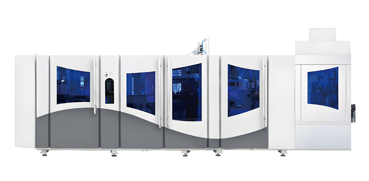
Yield discipline delivers the most when the machine underneath it is designed for repeatability. YuDa, a Wanplas factory with more than twenty years of specialization in PET bottle blow molding machines, exports to more than sixty countries and holds more than twenty patents covering its clamping, heating and control architecture. Three design characteristics matter specifically for finished product rate: a unique cam linking system that integrates mold opening, mold locking and bottom mold elevation into a single coordinated movement, a high-speed servo driving system that makes stretch rod motion repeatable cycle after cycle, and an oven design with heater distance minimized to 38.1 mm that gives a sharper, more controllable vertical temperature profile.
FGX Series High-Speed Machines: 8000 to 15000 BPH
The FGX series is YuDa’s high-speed platform, built for beverage and water plants running long, stable campaigns where every point of first-pass yield is multiplied by very large volumes. Single-mold speed reaches 2500 to 3000 BPH, so cavity count sets the line rate. Because high output compresses the heating time available per preform, the FGX oven carries a high lamp count with fine vertical zoning, servo-controlled preform rotation and a cooling plate system that protects the preform surface while the core equalizes. The cam linking system reduces the number of independent movements that can drift out of synchronization, which is the mechanical root of many intermittent defects on high-speed lines.
For a plant chasing 99 percent first-pass yield, the practical advantages of the FGX platform are parameter repeatability and recipe control. Servo stretch motion means the rod profile is identical on cycle one and cycle one million. Independent zone control means the oven profile can be shaped rather than merely set. The remote monitoring system lets engineers at the China headquarters review PLC data and feed abnormality analysis back to the customer site, which shortens the diagnostic loop when a plant sees an unexplained yield shift.
| Specification | FGX-3 | FGX-4 | FGX-5 | FGX-6 |
|---|---|---|---|---|
| Cavities | 3 | 4 | 5 | 6 |
| Output, 500 ml bottle | 7500 to 9000 BPH | 10000 to 12000 BPH | 12500 to 14000 BPH | Up to 15000 BPH |
| Single-mold speed | 2500 to 3000 BPH | 2500 to 3000 BPH | 2500 to 3000 BPH | 2500 to 3000 BPH |
| Applicable bottle volume | 100 ml to 2 L | 100 ml to 2 L | 100 ml to 1.5 L | 100 ml to 1.5 L |
| Heating lamp quantity, indicative | Approximately 60 to 72 | Approximately 72 to 90 | Approximately 84 to 100 | Approximately 96 to 120 |
| Heating zones per oven module | Multi-zone, independently adjustable | Multi-zone, independently adjustable | Multi-zone, independently adjustable | Multi-zone, independently adjustable |
| Heater distance | 38.1 mm | 38.1 mm | 38.1 mm | 38.1 mm |
| Installed power, indicative | Approximately 100 to 125 kW | Approximately 120 to 150 kW | Approximately 140 to 170 kW | Approximately 160 to 195 kW |
| High pressure blowing air | 2.5 to 4.0 MPa | 2.5 to 4.0 MPa | 2.5 to 4.0 MPa | 2.5 to 4.0 MPa |
| Operating air pressure | 0.7 to 0.9 MPa | 0.7 to 0.9 MPa | 0.7 to 0.9 MPa | 0.7 to 0.9 MPa |
| Chilled water temperature | 8 to 15 degrees Celsius | 8 to 15 degrees Celsius | 8 to 15 degrees Celsius | 8 to 15 degrees Celsius |
| Overall dimensions, indicative | Approximately 5.0 by 2.6 by 2.4 m | Approximately 5.6 by 2.8 by 2.5 m | Approximately 6.2 by 3.0 by 2.5 m | Approximately 6.8 by 3.2 by 2.6 m |
| Drive and control | High-speed servo stretch, PLC with recipe storage, remote monitoring | High-speed servo stretch, PLC with recipe storage, remote monitoring | High-speed servo stretch, PLC with recipe storage, remote monitoring | High-speed servo stretch, PLC with recipe storage, remote monitoring |
Specifications above are indicative configurations for planning purposes. Final lamp count, installed power and machine footprint are confirmed against the specific bottle design, preform weight, target output and site electrical conditions at the order stage.
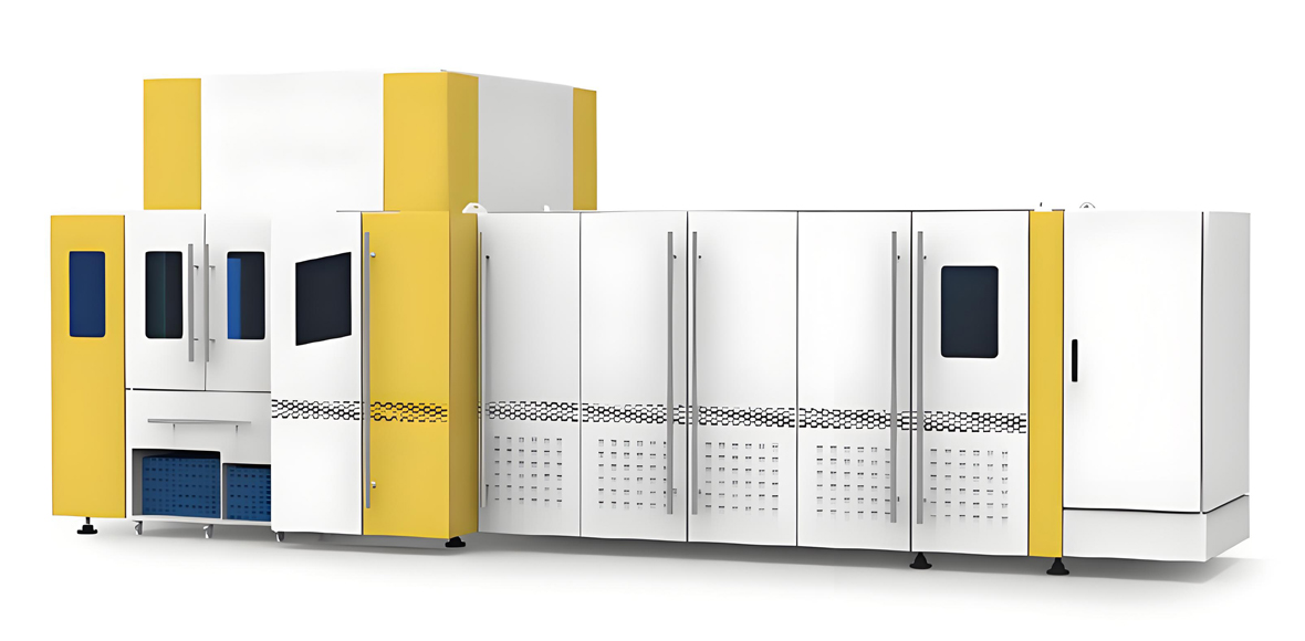
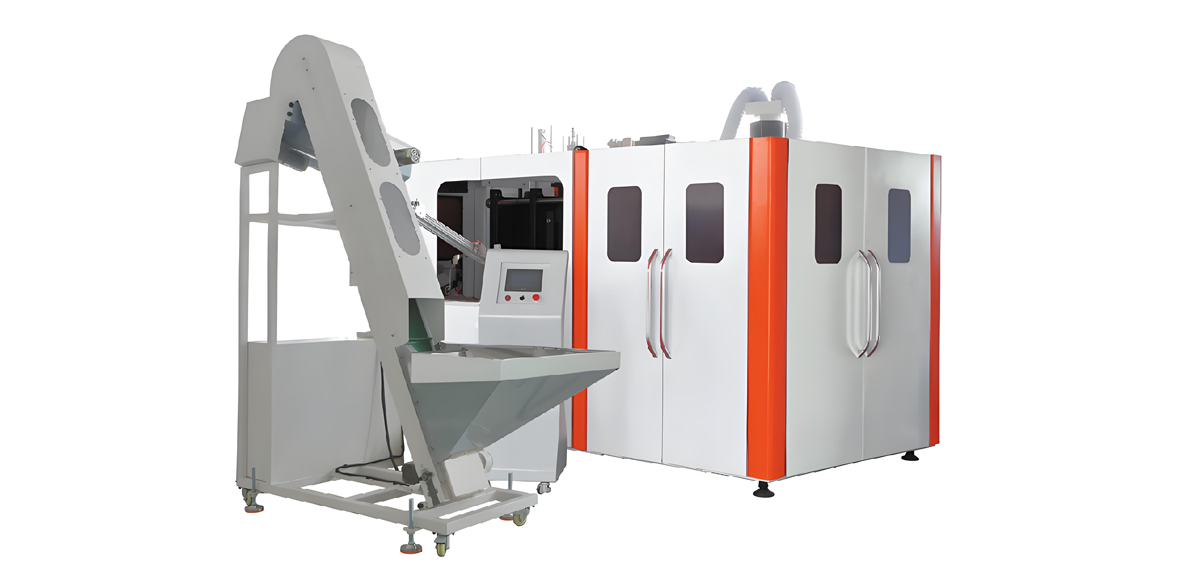
Standard Speed Full Automatic Series: 1000 to 7000 BPH
The Standard Speed full automatic series covers the broad middle of the market, where plants run several SKUs, change molds regularly and need dependable yield across a wide bottle range rather than maximum output on a single format. This is the platform most edible oil, household chemical, condiment and regional beverage producers select, and it is also where the yield discipline described in this article pays back fastest, because changeover frequency is high and every changeover is an opportunity to lose or protect yield.
Machines in this series use the same energy-saving oven concept with minimized heater distance and the same modularized construction, so changeovers stay short and repeatable. Larger cavity volume options extend the range up to 5 L and beyond for edible oil and household chemical containers, where wall distribution control matters more than cycle speed. Because these machines handle a wider bottle envelope, the recipe library becomes the plant’s most valuable asset: a well-maintained set of frozen recipes turns a two-hour changeover struggle into a twenty-minute mechanical operation followed by first-article approval.
| Specification | 1-cavity | 2-cavity | 4-cavity | 6-cavity |
|---|---|---|---|---|
| Output, 500 ml bottle | 1000 to 1500 BPH | 2000 to 3000 BPH | 4000 to 5500 BPH | 6000 to 7000 BPH |
| Applicable bottle volume | 100 ml to 5 L, larger on request | 100 ml to 5 L | 100 ml to 2 L | 100 ml to 2 L |
| Typical applications | Edible oil, household chemical, sample runs | Edible oil, condiment, juice, regional water | Water, juice, condiment, daily chemical | Water, carbonated soft drinks, juice |
| Heating lamp quantity, indicative | Approximately 14 to 24 | Approximately 24 to 36 | Approximately 40 to 56 | Approximately 56 to 72 |
| Heating zones | Multi-zone, independently adjustable | Multi-zone, independently adjustable | Multi-zone, independently adjustable | Multi-zone, independently adjustable |
| Heater distance | 38.1 mm | 38.1 mm | 38.1 mm | 38.1 mm |
| Installed power, indicative | Approximately 25 to 40 kW | Approximately 45 to 65 kW | Approximately 75 to 100 kW | Approximately 100 to 130 kW |
| High pressure blowing air | 2.5 to 4.0 MPa | 2.5 to 4.0 MPa | 2.5 to 4.0 MPa | 2.5 to 4.0 MPa |
| Operating air pressure | 0.7 to 0.9 MPa | 0.7 to 0.9 MPa | 0.7 to 0.9 MPa | 0.7 to 0.9 MPa |
| Chilled water temperature | 8 to 15 degrees Celsius | 8 to 15 degrees Celsius | 8 to 15 degrees Celsius | 8 to 15 degrees Celsius |
| Overall dimensions, indicative | Approximately 3.0 by 1.8 by 2.0 m | Approximately 3.6 by 2.0 by 2.1 m | Approximately 4.6 by 2.4 by 2.3 m | Approximately 5.4 by 2.6 by 2.4 m |
| Changeover concept | Modularized tooling, stored recipes | Modularized tooling, stored recipes | Modularized tooling, stored recipes | Modularized tooling, stored recipes |
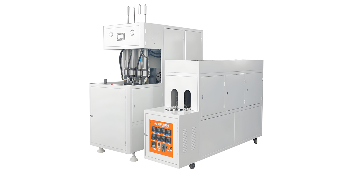
For very small producers, seasonal packers and plants that need a low-capital entry point, the YuDa semi-automatic series remains a practical option. Semi-automatic machines separate heating and blowing into operator-assisted steps, which lowers procurement cost and simplifies maintenance, at the cost of a stronger dependence on operator technique for yield. Plants running semi-automatic equipment should invest correspondingly more in operator training, written parameter cards and first-article discipline, because the human element carries a larger share of the process control burden.
Application Industries and End Products
Flat blow molding serves every cold-filled liquid category, and each category places a different weighting on the defect list. Understanding which defects matter most for the target market lets a plant allocate inspection effort where it actually protects revenue.
- Drinking water and mineral water. Lightweight 330 ml to 2 L bottles, extremely high volume, thin walls and aggressive lightweighting. The dominant risks are pearlescence, paneling and volume variation. Clarity is a purchasing criterion, so haze control and preform quality carry disproportionate weight. This category is the natural home of the FGX high-speed platform.
- Carbonated soft drinks. Petaloid base bottles from 250 ml to 2.5 L. Burst pressure, base stress cracking and creep under sustained pressure dominate. Base mold temperature control, gate zone heating and stress crack testing are non-negotiable, and the CTQ list expands to include base clearance.
- Juice and beverages. Frequently 250 ml to 1.5 L with more complex body geometry, ribs and shoulder features. Detail definition, venting and material distribution around features are the main challenges, and label panel diameter tolerance tightens.
- Edible oil. Typically 500 ml to 5 L, heavier preforms, thicker walls, strong emphasis on top load for stacked distribution and on clarity for shelf appeal. Slower cycles and larger volumes suit the Standard Speed series with large-volume configuration.
- Daily chemical and household products. Detergent, shampoo, cleaner and personal care bottles with irregular shapes, handles and flat panels. Wall distribution around non-round geometry is the main yield challenge, and chemical compatibility of the closure system matters at the design stage.
- Condiments and sauces. Soy sauce, vinegar, cooking wine and syrup bottles from 150 ml to 5 L. Wide-mouth finishes, hot handling in the customer’s plant and stacking strength drive the specification, and finish integrity carried over from the preform is critical.
- Pharmaceutical and health drinks. Smaller bottles with tight dimensional tolerance and strict cleanliness expectations. Inspection intensity rises and contamination control in the workshop becomes a formal requirement rather than good practice.
Across all of these categories, the yield logic is identical even though the defect weighting differs: control the preform, shape the oven profile deliberately, keep the pre-blow relationship centered, hold the mold thermally stable, and measure enough to see drift before it becomes scrap.
Requirement to Model Selection Guidance
Machine selection influences achievable yield more than most buyers expect, because a machine running near its speed ceiling on a difficult bottle has no margin for the small variations that daily production always produces. The table below maps typical requirement profiles to the YuDa lineup, with yield-relevant notes attached to each recommendation.
| Target output | Bottle volume | Bottle complexity | Recommended YuDa configuration | Yield-relevant note |
|---|---|---|---|---|
| Below 1500 BPH | 500 ml to 5 L | Simple to moderate | Semi-automatic series, or Standard Speed 1-cavity | Operator technique dominates yield; invest in training and parameter cards |
| 2000 to 3000 BPH | 500 ml to 5 L | Moderate, multiple SKUs | Standard Speed 2-cavity full automatic | Changeover discipline and stored recipes are the main yield levers |
| 4000 to 5500 BPH | 100 ml to 2 L | Moderate | Standard Speed 4-cavity full automatic | Cavity-level SPC becomes essential from this point upward |
| 6000 to 7000 BPH | 100 ml to 2 L | Moderate to complex | Standard Speed 6-cavity full automatic | Oven zoning precision starts to limit yield before machine speed does |
| 7500 to 9000 BPH | 100 ml to 2 L | Moderate to complex | FGX-3 high-speed | Servo stretch repeatability protects distribution at higher speed |
| 10000 to 12000 BPH | 100 ml to 2 L | Water and CSD, stable SKU | FGX-4 high-speed | Preform supply consistency becomes the limiting yield factor |
| 12500 to 14000 BPH | 100 ml to 1.5 L | Water and CSD, stable SKU | FGX-5 high-speed | Compressed air quality and chilled water capacity must be sized generously |
| Up to 15000 BPH | 100 ml to 1.5 L | Single dominant SKU | FGX-6 high-speed | Automated inspection and inline leak detection are strongly recommended |
| Water plant, integrated filling | 200 ml to 2 L | Simple | Blow-fill-cap combined solution | Removes bottle handling damage between blowing and filling |
| Compact plant, limited floor area | 200 ml to 1.5 L | Simple | Linear blow-fill-cap combi block | Fewer transfer points means fewer finish scuffing defects |
| Edible oil, 5 L focus | 3 L to 5 L | Moderate, handle features | Standard Speed 1-cavity or 2-cavity, large volume configuration | Wall distribution around the handle area drives the parameter window |
Systematic Improvement Across People, Machine, Material, Method and Environment
Sustainable yield improvement is a management system, not a parameter set. Plants that reach the 99 percent band and stay there have addressed all five contributing domains rather than optimizing one and hoping the rest follow.
People: Skills Matrix, SOPs and First-Article Discipline
Operator capability is measurable and manageable. A simple skills matrix listing each operator against each competency, such as oven profiling, changeover, section weighing, defect identification and first-article approval, immediately reveals where a shift is exposed. Most plants discover that their best shift and their worst shift differ by two or three trained individuals rather than by anything mechanical.
Standard operating procedures should be short, visual and specific to the bottle. A one-page parameter card per SKU showing the frozen recipe, the boundary sample photographs of acceptable and unacceptable appearance, the CTQ tolerances and the reaction rules does more for yield than a thick manual nobody opens. First-article approval must be a hard gate: no production is released after a startup or changeover until a full cavity set has been measured and signed off. This single rule eliminates the largest category of avoidable batch scrap.
Machine: Preventive Maintenance and Daily Checks
A daily check sheet completed at shift start catches most emerging problems while they are still free to fix. The essential items are mandrel rotation on all positions, lamp function with no failed tubes, cooling plate airflow, chilled water supply temperature at the machine, compressed air pressure and drain condition, stretch rod alignment and cleanliness, mold vent condition, and neck support tooling wear. Each item takes seconds; together they prevent the majority of unexplained mid-shift yield drops.
Preventive maintenance beyond the daily check should follow running hours rather than the calendar. Lamp replacement, valve block servicing, filter replacement, mold refurbishment and toggle inspection all have characteristic intervals that a plant learns within the first year. Recording the failure that eventually occurs and working backward to set the interval is more effective than adopting generic schedules.
Material, Method and Environment
Material discipline means one preform specification per bottle, verified at receipt, conditioned before use and traced by lot into every production record. When a yield event occurs, the ability to say which preform lot was running is often the difference between a two-hour investigation and a two-week one.
Method discipline means the recipe is the authority. Parameters are changed by engineering approval, changes are logged with the reason and the resulting section weights, and the recipe file is updated so that the next startup begins from the improved state rather than from memory. Environment discipline means the workshop temperature and humidity are controlled and recorded, the preform staging area is protected, and housekeeping keeps dust away from lamps, reflectors, vents and cooling plates. None of these are glamorous, and together they are worth more than most equipment upgrades.
Ramp-Up and Steady-State Management
New bottle designs and new production lines pass through a predictable yield curve, and the plants that manage the curve deliberately reach the mature band in weeks rather than months. The uncontrolled alternative is a long plateau in the mid-90s that everyone accepts as normal.
The Four-Stage Trial Sequence for a New Bottle
Stage one is sampling: the mold is proven, the bottle is blown at deliberately conservative settings, and the objective is a dimensionally correct bottle rather than a fast one. Stage two is parameter fixing: oven zones are adjusted one at a time with section weighing as the feedback, the pre-blow relationship is centered, and the working window is mapped by deliberately walking each key parameter to the point where defects appear, then returning to the middle. Knowing where the edges are is what allows confident operation in the center.
Stage three is small-batch validation: several hours of continuous production with full CTQ measurement, capability calculation and the complete functional test set, including whatever aging tests the product requires. Stage four is mass production release, at which point the recipe is frozen, the parameter card is issued, the boundary samples are photographed and archived, and the SKU enters the routine SPC system. Skipping stage two, which is the stage that feels least productive because it generates scrap on purpose, is the most common reason a bottle never stabilizes.
Recipe Archiving and Retrieval
Every stable SKU should exist as a stored recipe containing oven zone values, chain speed, pre-blow pressure and timing, high pressure value and timing, exhaust delay, stretch rod parameters, mold and base temperatures, plus the seasonal offsets. Recipes must be version controlled, because an undocumented tweak that seemed helpful last August will otherwise become part of the permanent configuration without anyone deciding that it should. YuDa control systems support recipe storage and retrieval so that a changeover restores a qualified state rather than starting a fresh negotiation between the operator and the machine.
Steady-state management is then mostly about detecting drift. The three most useful drift indicators are the hourly bottle weight chart per cavity, the shift section weight distribution, and the weekly functional test trend. When those three agree that something is moving, the plant investigates before the scrap arrives. When they disagree, the measurement system itself is usually the problem, and verifying gauges and operator technique comes first.
Quantified Improvement Roadmap
Not every improvement action carries the same return, and plants with limited engineering time need to sequence their work. The roadmap below ranks common actions by the first-pass yield improvement typically observed when the action is implemented on a line that was previously neglecting it, together with implementation difficulty and relative investment level. Actual results vary by starting condition, and a line already doing an item well will gain nothing by doing it again.
| Improvement action | Typical yield gain, percentage points | Implementation difficulty | Relative investment | Time to visible effect |
|---|---|---|---|---|
| Enforce first-article approval at every startup and changeover | 0.5 to 1.5 | Low | Low | Immediate |
| Introduce incoming preform acceptance inspection | 0.8 to 2.0 | Low | Low | One to two weeks |
| Condition preforms to workshop temperature before unbagging | 0.3 to 1.2 | Low | Low | Immediate |
| Daily mandrel rotation and lamp function check | 0.3 to 0.8 | Low | Low | Immediate |
| Freeze recipes and version control parameter changes | 0.4 to 1.0 | Low | Low | Two to four weeks |
| Cavity-level bottle weight SPC with written reaction rules | 0.5 to 1.5 | Medium | Low | Two to four weeks |
| Systematic oven zone profiling with section weighing | 0.8 to 2.5 | Medium | Low | One to three weeks |
| Center the pre-blow timing window and map process edges | 0.5 to 2.0 | Medium | Low | One to two weeks |
| Mold vent cleaning and parting face maintenance schedule | 0.2 to 0.8 | Low | Low | Immediate |
| Separate base mold cooling circuit control | 0.3 to 1.0 | Medium | Medium | Two to six weeks |
| Compressed air filtration and drying upgrade | 0.2 to 0.9 | Medium | Medium | Two to four weeks |
| Chilled water capacity and distribution improvement | 0.3 to 1.2 | Medium | Medium | Four to eight weeks |
| Workshop temperature and humidity control in the staging area | 0.3 to 1.0 | Medium | Medium | Four to twelve weeks |
| Operator skills matrix and structured training program | 0.5 to 1.5 | Medium | Low | Four to twelve weeks |
| Inline leak detection and automated bottle inspection | 0.2 to 0.6 first pass, large complaint reduction | High | High | Eight to sixteen weeks |
| Upgrade to servo-driven high-speed platform with recipe control | 0.5 to 2.0 | High | Very High | Project dependent |
| Bottle redesign to correct an out-of-window stretch ratio | 1.0 to 3.0 | High | Premium | Project dependent |
The pattern in this table is consistent with what most plants find in practice: the largest early gains come from low-investment discipline items, and capital projects only outperform them once the discipline items are already in place. A plant that installs automated inspection while still accepting unverified preforms has bought a very expensive way of counting its own defects.
Compliance, Service and Support
Yield and compliance are connected, because a bottle that fails a food contact or dimensional requirement is scrap regardless of how it looks. Flat blow molded bottles for food and beverage use are produced from bottle-grade PET resin intended for food contact, and plants typically work within the FDA food contact framework for the United States market, GB 4806 for the Chinese market and equivalent regional requirements elsewhere. Quality system certification to ISO 9001 provides the documentation discipline that makes recipe control, calibration and traceability auditable rather than informal. Machine safety and electrical construction should meet the requirements applicable in the destination market, and calibration of balances, pressure gauges, thickness gauges and temperature instruments should follow a documented schedule, since uncalibrated measurement quietly corrupts every decision built on it.
What YuDa Provides Around the Machine
Equipment support has a direct effect on yield, because most yield losses are diagnostic problems rather than hardware failures, and the speed of diagnosis determines how much scrap is produced before the fix. YuDa’s support package is built around that reality.
- Testing before shipment. Every machine is run and inspected at the factory before delivery, with the customer’s bottle design and preform where these are supplied in advance, so the machine arrives with a proven baseline recipe rather than a blank control system.
- Installation and commissioning. Engineers attend the site to install, commission and hand over the line, including initial oven profiling on the customer’s actual preforms and ambient conditions.
- Operator and technician training. Training covers defect identification, oven zone adjustment logic, section weighing method, changeover procedure and daily checks, which is exactly the skill set the yield system depends on.
- Spare parts policy. As part of the Wanplas brand commitment, customers receive USD 500 in free parts every year, with free replacement of parts damaged within the warranty period.
- Remote monitoring and support. The remote monitoring system allows engineers at the China headquarters to review PLC data, analyze abnormal behavior and feed findings back to the customer site, shortening the diagnostic loop when yield shifts without an obvious cause.
- Open factory policy. Wanplas and its factories welcome customer visits. Prospective buyers are encouraged to see machines being assembled and tested, and to run trial blowing on their own preforms before committing.
- Wanplas brand guarantees. Transportation guarantee, production capacity guarantee and quality standards guarantee apply across the group, alongside the shared commitment expressed in the Wanplas mission to warm global customers with China plastic machinery.
Frequently Asked Questions
What first-pass yield should a mature PET flat blow molding line achieve?
A mature line running a stable bottle design on qualified preforms should hold first-pass yield between 98.5 and 99.5 percent measured at the blower discharge, with startup and changeover losses counted separately. New lines typically start between 92 and 96 percent during ramp-up. Reaching the mature band usually takes four to eight weeks of disciplined parameter fixing, first-article gating and cavity-level measurement, not months of trial and error.
Why do PET bottles turn pearly white during blowing?
Pearlescence is stress whitening caused by micro-voiding when the material is stretched beyond its natural stretch limit at the temperature it was given. The usual causes are insufficient preform preheat, an excessive stretch ratio, pre-blow air applied too early, or cold preforms taken directly from storage. Raise body zone lamp power in small steps, delay pre-blow onset by a few milliseconds, and confirm that preforms are conditioned to workshop temperature before they enter the oven.
What preform intrinsic viscosity should I specify for flat blow molding?
Bottle-grade PET resin between 0.76 and 0.84 dL/g covers most flat blow molding applications. The 0.76 to 0.78 band suits lightweight still water bottles where stretch is moderate, while 0.80 to 0.84 dL/g suits carbonated soft drinks and larger edible oil containers that need higher melt strength during preform injection and better stress crack resistance in service. Never mix IV grades within a single run, because the two populations need different oven profiles.
How do I diagnose uneven wall thickness in a PET bottle?
Start by sectioning the bottle into horizontal bands and weighing each band, then compare quadrant weights within the same band to separate vertical distribution problems from circumferential ones. Vertical imbalance points at oven zone profiling and pre-blow timing. Circumferential imbalance points at mandrel rotation failure, fouled reflectors or preform wall eccentricity. Repeating the measurement per cavity isolates whether the problem is line-wide or belongs to one station.
What causes base stress cracking on carbonated PET bottles?
Base stress cracking is driven by thick, poorly oriented material around the gate combined with residual stress and sustained internal pressure, often accelerated by contact with cleaning chemicals. Increase gate zone preheat slightly, verify that the stretch rod contacts the preform base centrally and at the correct speed, hold base mold temperature in the lower half of the 8 to 15 degree Celsius range, and check material distribution through the standing ring by section weighing. Run periodic stress crack resistance testing rather than relying on burst pressure alone.
Do I need automatic inspection equipment to reach high yield?
Not initially. Most plants operating below 97 percent first-pass yield gain far more from incoming preform inspection, first-article gating, oven profiling and cavity-level weight charts, all of which cost very little. Automated inspection and inline leak detection are valuable for protecting the customer from escapes and for very high-speed lines, but they detect defects rather than prevent them. Install prevention first, then detection.
How long should preforms rest between injection and blowing?
A conditioning window of 24 to 48 hours after injection is standard practice, because preform dimensions and the neck finish continue to stabilize after molding. Blowing preforms that are only a few hours old produces different results from blowing the same preforms two days later. Enforce the rule through warehouse lot dating rather than operator judgment, particularly in plants where preform injection and blowing sit under the same roof.
Does a higher speed machine make yield harder to control?
Higher output compresses the heating time available per preform, so oven design, lamp zoning and rotation uniformity carry more weight. That is a design requirement, not a penalty. A high-speed platform with tight heater pitch, fine vertical zoning, servo-controlled stretch motion and stored recipes typically holds better parameter repeatability than a slower machine adjusted by hand, so yield is equal or better provided preform supply and utility capacity are matched to the speed.
What should I check first when yield drops suddenly overnight?
Work from the largest and simplest variables down. Check whether the preform lot changed, whether workshop temperature or humidity shifted, whether any lamp has failed, whether all mandrels rotate, whether chilled water supply temperature is at set point, and whether compressed air pressure and dryness are normal. Only then examine the recipe log to see whether a parameter was altered. Sudden changes almost always have a discrete cause, and parameter tuning before the cause is found simply creates a second problem.
Conclusion
Improving the finished product rate of PET flat blow molding bottle production is an engineering problem with a well-mapped solution path. Define yield honestly at the blower discharge and separate first-pass yield from rework and startup loss so the numbers can drive action. Classify every defect into appearance, dimensional or functional categories and work the Pareto rather than the anecdote. Control the preform as if it were the product, because in a two-step process it is: intrinsic viscosity between 0.76 and 0.84 dL/g, moisture below 50 ppm at injection, weight within plus or minus 0.5 percent, sound neck crystallization, and 24 to 48 hours of conditioning before blowing. Shape the oven profile deliberately zone by zone with section weighing as the feedback, center the pre-blow timing window, and hold stretch ratios inside the 2.8 to 3.2 axial and 3.5 to 4.5 radial bands that give clean biaxial orientation. Keep the mold thermally stable between 8 and 15 degrees Celsius with independent base control, vents open and parting faces true. Then prove it statistically with cavity-level Cp and Cpk of at least 1.33 on the CTQ set, and confirm it functionally with a testing program whose results are recorded as numbers and trended weekly.
The machine underneath this system matters because it sets the ceiling. YuDa, a Wanplas factory with more than twenty years of PET bottle blow molding specialization, more than twenty patents and installations in over sixty countries, builds that ceiling high through servo-driven stretch motion, a cam linking system that coordinates mold opening, locking and base elevation in one movement, oven design with heater distance minimized to 38.1 mm, modularized construction for fast repeatable changeovers, and remote monitoring that shortens the diagnostic loop when something moves. The FGX high-speed series covers 8000 to 15000 BPH for water and carbonated beverage plants running long stable campaigns, while the Standard Speed full automatic series covers 1000 to 7000 BPH for multi-SKU producers in edible oil, condiment, juice and household chemical packaging, with semi-automatic machines available where capital intensity must stay low.
If you are planning a new flat blow molding line or trying to move an existing one from acceptable yield into the 99 percent band, share your bottle drawing, preform specification, target output and SKU mix, and the YuDa engineering team will propose a matched configuration, define the expected process window for your bottle, and arrange a trial run on your own preforms at the factory. Visitors are welcome to see machines assembled, tested and running before making any commitment, and every installation carries the Wanplas brand promises, including installation and commissioning support, operator training, remote diagnostics and USD 500 in free parts every year. Send your specifications and let the numbers decide.