Building a PET packaging bottle factory is far more than buying a stretch blow molding machine and finding a vacant shed. The workshop itself is a piece of production equipment. Its layout, air quality, utilities, and material flow determine whether a PET bottle line runs at rated output with low rejection rates or struggles with condensation, contamination, unstable bottle weight, and chronic downtime. YuDa, a Wanplas factory, has spent more than 20 years supplying PET bottle blow molding machines to more than 60 countries and holds more than 20 patents as one of the top two PET bottle blow machine manufacturers in China. This guide distills that field experience into a practical standard for workshop construction, covering site layout, clean zones, HVAC, compressed air, cooling water, electrical power, floor loading, utilities, and workflow. Whether you are planning a greenfield plant or retrofitting an existing hall, the requirements below help you build a workshop that matches the capabilities of a modern automatic PET blow molding line rather than fighting against them.
1. The Role of Workshop Design in a Profitable PET Bottle Plant
A PET bottle production line is a chain of dependent processes: preform feeding and conditioning, infrared heating, stretch blow molding, bottle conveying, filling, capping, labeling, and packing. Each step imposes conditions on the building around it. The heating oven wants stable ambient temperature and clean air. The blow molder wants dry, oil-free high-pressure air. The mold wants precise-temperature cooling water. The filling interface wants a protected, positive-pressure clean zone. If the workshop fails any single condition, the whole line loses output and quality.
Well-planned construction pays back quickly. A correctly sized compressed air system reduces per-bottle energy cost. A clean, unidirectional workflow cuts manual handling and rejection. A slab and ceiling designed for the real equipment load avoids expensive later reinforcement. YuDa’s own engineering data shows that its FGX-series high-speed machines, with heater spacing minimized to 38.1 millimeters and a servo cam-linking system, already save more than 30 percent of electricity compared with conventional heating ovens; but those savings are only realized when the surrounding workshop supplies stable power, clean dry air, and consistent cooling water. In other words, the machine and the building must be designed as one system.
The sections that follow take each building system in turn, give the engineering basis, and present reference specification tables you can hand to your architect, HVAC contractor, and utility engineer. The values are typical for a PET bottle plant producing water, carbonated soft drinks, edible oil, juice, dairy, and household-chemical bottles on automatic or semi-automatic lines.
2. Site Selection and Overall Plant Layout
Site selection sets the ceiling on what your workshop can achieve. Choose a parcel with reliable three-phase grid power, adequate water supply and drainage, good road access for container trucks, and enough land for expansion. Avoid sites prone to flooding, with high groundwater that complicates a deep foundation, or adjacent to heavy dust, odor, or chemical sources that would threaten bottle hygiene. A PET bottle plant does not need a classically classified cleanroom for most products, but it does need to keep the blowing-to-filling environment clean, dry, and controllable.
The overall layout should organize the plant as a long, single-direction production river. Raw material or preforms enter at one corner, move through conditioning and blowing, then filling, labeling, and packing, and leave as finished pallets at the opposite corner. Administrative offices, labs, and change rooms sit on the clean side near filling; receiving, scrap handling, and maintenance sit on the dirty side. The goal is to make it physically impossible for a forklift carrying returned pallets to cross the path of a worker carrying sanitized bottles.
The table below maps the functional zones of a standard PET bottle workshop and the area each typically demands. These are planning ranges; a specific layout should be developed from your target output, shift pattern, and pallet buffer strategy.
Functional Zone Allocation for a Standard PET Bottle Workshop
| Functional Zone | Typical Share of Built Area | Key Requirement | Hygiene Class |
|---|---|---|---|
| Preform receiving and storage | 10 to 15 percent | Dry, pest-controlled, FIFO racking | General / controlled |
| Blowing hall (blow molders) | 20 to 28 percent | Stable temp, clean air, utility trenches | Controlled clean zone |
| Filling and capping interface | 12 to 18 percent | Positive pressure, enclosed transfer | ISO Class 8 minimum |
| Labeling, packing, palletizing | 12 to 16 percent | Conveyor routing, carton buffer | General |
| Finished-goods warehouse | 18 to 25 percent | FIFO, truck docking | General |
| Utility and compressor room | 8 to 12 percent | Ventilation, vibration isolation | General / enclosed |
| Change rooms, labs, offices | 6 to 10 percent | Airlock gowning, QC lab | Clean side |
A common mistake is to under-allocate the utility room and the finished-goods buffer. Air receivers, compressors, dryers, a water chiller, an electrical panel, and a spare-parts cabinet together need substantial floor area and service clearance. Equally, finished-goods buffer space protects the line from stoppages caused by truck scheduling. Plan both generously from the start.
3. Clean Zones and Hygiene Control
For most PET bottled water, edible oil, and household-chemical products, the plant does not require a fully classified pharmaceutical cleanroom. What it does require is a clearly defined clean zone around the blowing and filling operations, separated from the dirty receiving and packing areas by walls, airlocks, and a positive-pressure differential. The purpose is to keep airborne particles, insects, and microbial load away from the bottle interior at the moment the hot, stretched bottle is born and before it is sealed.
In a two-step process, preforms are molded off-site or in a separate room, then transported to the blow molder. The interface between the blow molder exit and the filler should be an enclosed, positively pressurized tunnel or chamber. In a combined blowing-filling-capping (BFC) block, the bottles are never exposed to the room air at all, which is the cleanest arrangement and the easiest to build because the clean envelope is small and integrated into the machine.
Hygiene control also includes personnel discipline. Operators entering the clean zone pass through a gowning airlock with hand sanitation, hairnets, and dedicated footwear. The change room should be on the clean side so that workers do not carry contamination from the warehouse. Pest control, drainage traps, and covered waste points complete the basic program.
Clean Zone Classification Reference
| Area | Air Quality Target | Pressure Differential | Access Control |
|---|---|---|---|
| Preform storage | Clean, dry, dust-controlled | Neutral | General access |
| Blowing hall | Filtered supply, low particle count | Slightly positive to outside | Gowned entry |
| Blow-to-fill interface | ISO Class 8 equivalent | Plus 10 to 15 Pa vs blowing hall | Airlocks, sanitized |
| Filling and capping | ISO Class 8, enclosed | Most positive in plant | Restricted, gowned |
| Packing and warehouse | General industrial | Negative to clean side | Open |
A practical rule: the cleanest air should always flow from filling toward packing and receiving, never the reverse. Design supply and exhaust accordingly, and verify the pressure cascade with a manometer during commissioning.
4. HVAC and Environmental Control
HVAC for a PET bottle plant is not about comfort alone; it is about stabilizing the process. The infrared heating oven conditions preforms to a precise temperature profile before stretching. If the ambient air in the blowing hall swings between cool mornings and hot afternoons, or if humidity varies, the preform surface temperature at the mold will drift and bottle wall thickness, base formation, and top-load strength will vary. Stable HVAC keeps the oven calibration valid across the shift.
Target a blowing-hall temperature of 22 to 26 degrees Celsius with tight control, and relative humidity of 40 to 60 percent. Lower humidity also helps the compressed air dryer and reduces condensation risk on cold water lines. The filling clean zone needs a higher air-change rate and HEPA-filtered supply at the ceiling, with returns low on the walls to sweep particles downward and out.
Ventilation must also remove heat generated by the ovens, compressors, and chiller. A PET blow molding line is a significant heat source; without planned extraction the hall will overheat in summer even with the supply air conditioned. Separate the compressor room ventilation from the blowing hall so that compressor heat and noise stay enclosed.
HVAC Parameter Reference
| Parameter | Blowing Hall | Filling Clean Zone | Compressor Room |
|---|---|---|---|
| Temperature | 22 to 26 degrees C | 21 to 24 degrees C | Exhaust to ambient |
| Relative humidity | 40 to 60 percent | 45 to 55 percent | Not controlled |
| Air changes per hour | 10 to 15 | 20 to 30 | 15 to 25 (exhaust) |
| Filtration | G4 to F7 supply | H13 HEPA at ceiling | Coarse intake |
| Pressure vs adjacent | Positive | Most positive | Negative (sealed) |
When the plant is in a hot and humid climate, size the dehumidification load from the worst summer design day, not the annual average. A humid hall defeats the air dryer and invites condensation on chilled-water pipes and on cold bottles after molding, which can fog labels and encourage microbial growth.
5. Compressed Air System Design
Compressed air is the lifeblood of a PET blow molding line, and getting it wrong is the single most common cause of poor bottle quality and high operating cost. A PET stretch blow molder uses two distinct air services. Low-pressure air, typically 8 to 10 bar, powers the pneumatic actuators, mold movements, conveyors, and valve operations. High-pressure air, typically 30 to 40 bar, is the actual stretch and blow medium that inflates the preform against the mold wall and sets the bottle shape.
The high-pressure air must be oil-free. Any oil mist carried into the bottle interior is a direct food-contact contaminant and a compliance failure for potable and edible-oil products. It must also be dry, with a pressure dew point of minus 20 degrees Celsius or lower, because moisture condensing inside the bottle causes haze, droplet marks, and microbial risk. A desiccant or heat-of-compression dryer on the high-pressure loop, plus a receiver sized for the surge demand of the blow, is non-negotiable.
The high-pressure demand is highly pulsed: each blow event draws a sharp slug of air. A properly sized high-pressure receiver and a booster compressor with a large buffer smooth these pulses so that line pressure does not sag during multi-cavity simultaneous blowing. Many plants recover and reuse the high-pressure exhaust from the bottle for low-pressure service, which can cut compressor energy substantially.
Compressed Air Specification Reference
| Service | Pressure | Oil Content | Dew Point | Typical Use |
|---|---|---|---|---|
| Low-pressure plant air | 8 to 10 bar | Oil-free preferred | Plus 3 degrees C | Actuators, conveyors |
| High-pressure blow air | 30 to 40 bar | Class 0 oil-free | Minus 20 degrees C | Stretch and blow |
| High-pressure receiver | 33 to 42 bar | N/A | N/A | Surge buffering |
| Piping | Rated to 45 bar | Stainless or coated | Sloped drain | Ring main |
Pipe the high-pressure air as a ring main with automatic drains so that condensate cannot accumulate and migrate to the machine. Avoid galvanized steel for the high-pressure blow loop because zinc dust can enter bottles; use stainless steel or certified clean-coated piping. Provide a point-of-use filter just before the machine air inlet as a final safeguard.
6. Cooling Water System Design
The blow mold must be cooled so that each bottle solidifies quickly and releases cleanly. Mold cooling water quality and temperature stability directly affect cycle time, bottle appearance, and dimensional consistency. A PET bottle plant therefore needs a dedicated, treated cooling water system rather than an open connection to municipal water.
Design a closed-loop chilled water circuit delivering 7 to 12 degrees Celsius to the mold temperature controllers. The exact setpoint depends on bottle size and output; smaller, thinner bottles tolerate warmer water, while large or base-heavy bottles need colder, more stable water to avoid deformation. Treating the water limits scaling and biological film inside the narrow mold channels, which would otherwise insulate the mold and lengthen cooling time.
The total cooling load combines the mold circuit, the air-compressor after-cooler, the chiller condenser rejection, and sometimes the hydraulic oil cooler. Size the chiller and cooling tower for the combined peak load with N-plus-one redundancy on the pump set so that a single pump failure does not stop production. A separate, open evaporative cooling tower may serve the chiller condenser, while the mold loop stays closed and clean.
Cooling Water Specification Reference
| Parameter | Mold Cooling Loop | Compressor After-cooler | Treatment Target |
|---|---|---|---|
| Supply temperature | 7 to 12 degrees C | Ambient plus 5 to 8 C | Stable, filtered |
| Total hardness | Below 100 ppm | Below 150 ppm | Softened |
| pH range | 7.0 to 8.5 | 7.0 to 8.5 | Corrosion inhibited |
| Pressure at machine | 3 to 5 bar | 3 to 5 bar | Constant |
| Loop type | Closed, glycol option | Open or closed | Biocide dosed |
Insulate all chilled-water piping to prevent condensation sweating that drips onto the line, and route the pipes in accessible trenches or overhead trays with drainage. A water-leak detection alarm in the utility trench protects the electrical infrastructure below.
7. Electrical Power and Distribution
A PET blow molding line is an electrically demanding consumer. The infrared heating oven, the servo drives, the air booster compressor, the chiller, and the conveyor motors together draw a significant and partly fluctuating load. The workshop must deliver clean, stable three-phase power and protect that supply from the voltage dips caused by compressor starts elsewhere in the plant.
Specify three-phase 380 to 480 volt power at 50 or 60 hertz according to the destination market. Each machine should have its own branch circuit with correctly rated breakers and a soft-start or variable-frequency control where applicable to limit inrush. The main incoming supply needs a transformer sized for the total connected load plus a margin for future lines; a common planning margin is 25 to 30 percent above the sum of nameplate powers.
Power quality matters for the control system. A voltage sag during a compressor start can reset a PLC and abort a production run. Install a standby diesel generator or at least an uninterruptible power supply on the control and servo cabinets so that brief outages ride through without loss of the running batch. Surge protection on the distribution board protects the sensitive servo amplifiers and HMI panels.
Electrical Power Requirement Reference by Line Type
| Line Type | Supply Voltage | Installed Power | With Compressor and Chiller | Backup Requirement |
|---|---|---|---|---|
| Semi-automatic series | 380 to 480 V, 3-phase | 15 to 25 kW | 40 to 70 kW | UPS on control |
| Standard-speed automatic | 380 to 480 V, 3-phase | 30 to 70 kW | 90 to 160 kW | UPS plus generator |
| FGX high-speed series | 380 to 480 V, 3-phase | 80 to 120 kW | 200 to 320 kW | Generator advised |
Route power in segregated cable trays separate from the data and air lines to avoid electromagnetic interference with the servo feedback. Provide a clearly labeled lockout-tagout disconnect at each machine, and ground the line, the mold, and the air receivers to a common earthing grid.
8. Floor Loading and Building Structure
The building structure is where many low-cost sheds fail a PET bottle project. A blow molding line, its air receivers, the booster compressor, the chiller, and the preform loader are heavy and concentrated. A standard industrial floor designed for light storage will crack and settle under this load, throwing the machine out of alignment and shortening bearing life.
Specify a reinforced concrete slab with a live load capacity of 1,500 to 2,500 kilograms per square meter across the production zone, and a thicker, pile or raft-supported section directly under the machine and air receivers where point loads are highest. A 300-millimeter slab over compacted subgrade is a common minimum; machine foundation plinths may need more. Keep the finished floor flat within a few millimeters over the machine footprint so that the blow molder stays level.
Ceiling height is another frequent omission. Plan a clear internal height of at least 6 meters to accommodate overhead conveyors, suspended air receivers, cable and pipe trays, and a future overhead crane for mold changes. The crane, even if added later, needs a runway embedded in the structure, so design the roof trusses for the lifting load from the start. Floor drains should slope to trapped, covered outlets so the washing of the filling zone does not pool or create a contamination path.
Building Structure Reference
| Element | Recommended Standard | Why It Matters |
|---|---|---|
| Floor live load | 1,500 to 2,500 kg per sq m | Supports machine and receivers |
| Slab thickness | 300 mm reinforced minimum | Prevents settlement and cracking |
| Clear ceiling height | 6.0 m or more | Overhead conveyors and crane |
| Floor flatness | Plus or minus 3 mm over machine | Machine alignment and wear |
| Utility trenches | Covered, drained, sealed | Air, water, cable routing |
| Crane runway | Designed for future lift | Mold and receiver handling |
Wall and roof construction should give a sealed, washable interior with insulated panels to hold the HVAC temperature and keep out pests. Avoid open trusses above the clean zone where dust can accumulate; a smooth ceiling with access walkway above is cleaner and easier to maintain.
9. YuDa PET Blow Molding Machine Modules
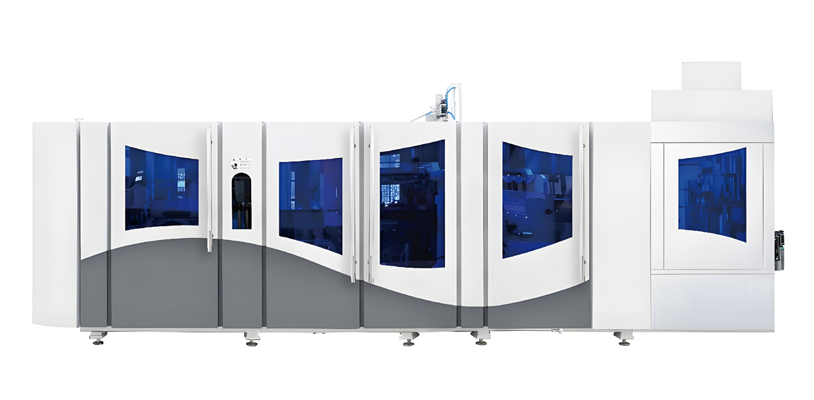
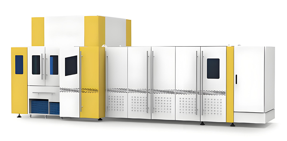
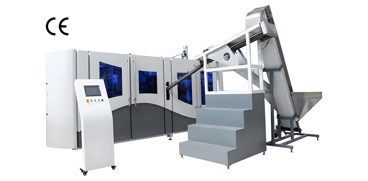
With the building systems defined, the choice of machine determines the detailed utility numbers. YuDa, a Wanplas factory, specializes in PET bottle blow molding machines and offers a complete range from semi-automatic units for small enterprises through standard-speed automatic lines to the FGX high-speed series for high-volume plants. All share the engineering features that make workshop planning predictable: a unique cam-linking system that integrates mold-opening, mold-locking, and bottom-mold elevation in one movement, a high-speed servo drive, a remote monitoring system, modular design for fast maintenance and changeover, and energy-saving ovens with the heater distance minimized to 38.1 millimeters for more than 30 percent electricity saving versus conventional ovens.
The two modules below are the ones most often specified for a new PET packaging bottle factory. Both are fully automatic, use mature and stable component brands, and integrate directly with the utility systems described in the previous sections.
Module A: FGX Series High-Speed PET Blow Molding Machine
The FGX series is YuDa’s high-speed configuration for plants that need 8,000 to 15,000 bottles per hour on a single line, with a single-mode speed of 2,500 to 3,000 bottles per hour per cavity. It is the right choice when the workshop is built around high output and tight energy budgets. The table lists the typical configuration range for planning the building services.
| Specification | FGX High-Speed Series (Typical Range) |
|---|---|
| Production capacity | 8,000 to 15,000 bottles per hour |
| Cavity number | 6 to 12 (single-mode 2,500 to 3,000 BPH per cavity) |
| Bottle volume range | 0.2 to 2.0 liters (water and CSD) |
| Preform neck standard | 28 mm PCO, 30/25, and custom |
| Heating oven | Infrared, heater spacing 38.1 mm, energy saving over 30 percent |
| Drive system | Servo cam-linking, high-speed |
| Installed power | 80 to 120 kW (machine only) |
| High-pressure air | 30 to 40 bar, oil-free, dew point minus 20 C |
| Low-pressure air | 8 to 10 bar |
| Cooling water | 7 to 12 C, 3 to 5 bar, treated |
| Machine dimensions | about 4,500 by 2,100 by 2,300 mm |
| Machine weight | 6,000 to 9,000 kg |
| Monitoring | Remote monitoring via PLC data on mobile |
Module B: Standard-Speed Fully Automatic PET Blow Molding Machine
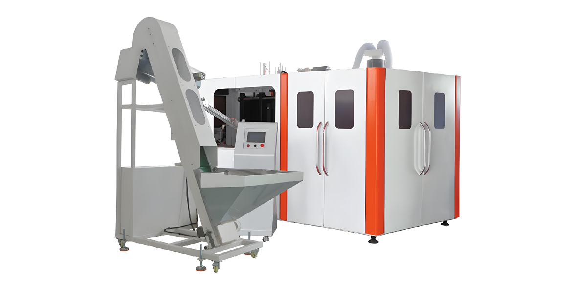
The standard-speed fully automatic series covers 1,000 to 7,000 bottles per hour, ideal for medium-sized plants, regional brands, and product mix that changes frequently. It carries the same cam-linking and modular architecture as the FGX series but with a lighter utility draw, which simplifies the workshop power and air design. For a first PET bottle factory, this series is often the most balanced choice between output and infrastructure cost.
| Specification | Standard-Speed Automatic (Typical Range) |
|---|---|
| Production capacity | 1,000 to 7,000 bottles per hour |
| Cavity number | 2 to 6 |
| Bottle volume range | 0.1 to 2.0 liters |
| Heating system | Advanced infrared, energy-saving lamps |
| Drive system | Servo or hybrid, cam-linking |
| Installed power | 30 to 70 kW (machine only) |
| High-pressure air | 30 to 40 bar, oil-free |
| Cooling water | 7 to 12 C, treated loop |
| Machine dimensions | about 3,600 by 1,600 by 2,000 mm |
| Machine weight | 3,500 to 5,500 kg |
| Changeover | Modular, fast mold swap |
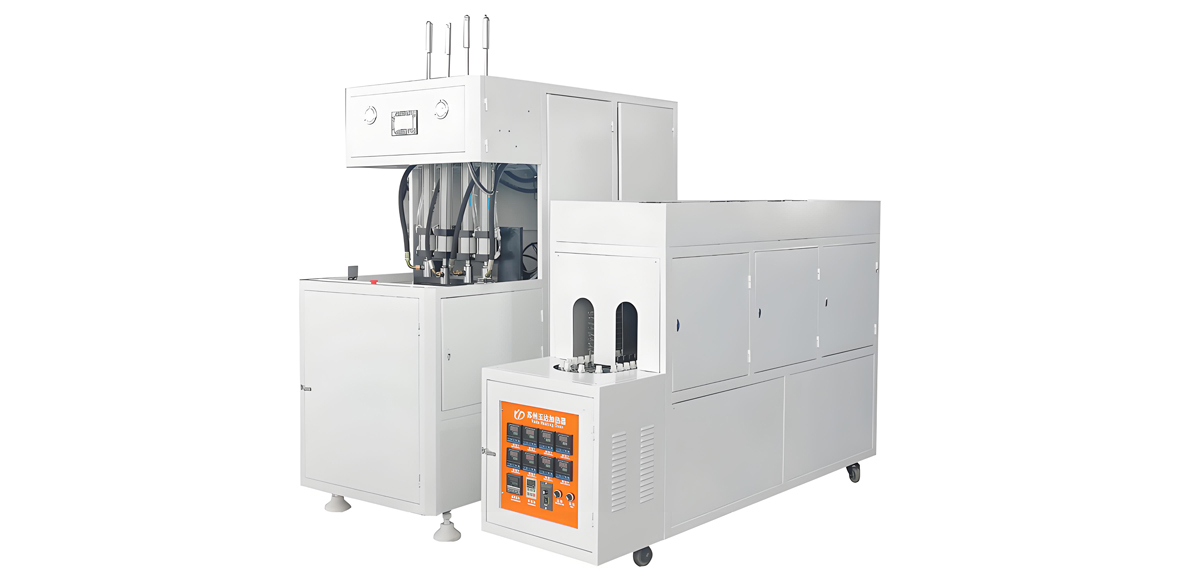
For the smallest entrants, YuDa’s semi-automatic series offers a lower procurement cost and a simpler utility profile, suitable for startups and low-volume specialty bottles. And for plants that want to minimize floor area and piping, the linear blowing-filling-capping CombiBlock and the bottle blow-filling-capping (BFC) machine integrate blowing and filling in one compact unit, which shrinks the clean envelope to almost nothing and simplifies the workshop layout dramatically.
10. Machine Selection Recommendation
Matching the machine to the business plan is the final step before the workshop is dimensioned. The table below maps common customer requirements to the recommended YuDa configuration. Use it together with the utility tables in sections 5 through 8 to size the building services.
Customer Requirement to Recommended Model
| Customer Need | Target Output | Bottle Size | Recommended YuDa Configuration |
|---|---|---|---|
| Small startup, low budget | Below 2,000 BPH | 0.2 to 2.0 L | Semi-automatic series |
| Regional brand, mixed SKU | 1,000 to 7,000 BPH | 0.1 to 2.0 L | Standard-speed fully automatic series |
| High-volume water or CSD | 8,000 to 15,000 BPH | 0.2 to 2.0 L | FGX high-speed series |
| Compact water line, limited area | Small to medium | 0.2 to 1.5 L | Linear blowing-filling-capping CombiBlock |
| Integrated blow and fill | Medium | 0.2 to 2.0 L | Bottle blow-filling-capping (BFC) machine |
11. Workflow and Material Flow Optimization
A well-built workshop is wasted if the workflow sends material back on itself. The governing rule is single-direction flow with no cross-traffic between dirty and clean zones. Preforms arrive at the receiving dock, move into storage, then into the blowing hall, then to filling and capping, then labeling and packing, then out to the finished-goods warehouse, which should be on the opposite side of the building from receiving.
Personnel circulation is a separate system. Operators and quality staff enter through the clean-side change rooms and stay within the blowing-to-filling envelope. Maintenance staff and forklift drivers handling empties or scrap use peripheral corridors that do not cross the clean interface. This separation is what keeps the ISO Class 8 target achievable without an expensive full cleanroom.
Buffer conveyors are essential. A stoppage at the labeler or palletizer should not force the blow molder to halt, because a halted molder still holds hot molds and preforms that can degrade. Provide accumulation tables between blowing, filling, and packing sized for at least several minutes of production, and design the line control so that upstream machines ramp down gracefully rather than tripping.
Vertical space helps. Overhead conveyors move bottles from blowing to filling above the floor, freeing the ground for maintenance access and forklift lanes, and keeping bottles away from floor-level contamination. Where the building uses a BFC or CombiBlock, much of this transfer is internal to the machine, which is the simplest workflow of all.
12. Application Industries for PET Bottles
PET is the dominant packaging plastic for clear, light, and shatter-resistant bottles, and a properly built PET bottle workshop serves a wide range of packaged-goods industries. YuDa PET blow molding machines produce bottles for the following application fields, each with its own hygiene and format expectations that the workshop must support:
- Drinking water: the largest PET application, from 0.3 liter personal bottles to 5 liter and 10 liter bulk containers, requiring the highest clarity and consistent base performance.
- Carbonated soft drinks: bottles needing higher wall stiffness and precise preform conditioning to survive internal pressure, demanding stable oven control from the HVAC system.
- Edible oil: hot-fill or ambient-fill cooking-oil bottles with wide mouths, where clean, dry air and oil-free contact are critical for food safety.
- Juice and dairy drinks: often filled hot or aseptically, placing extra demand on the clean filling interface and the pressure cascade.
- Household and personal care: detergents, shampoos, and cleaners in PET, where color and gloss matter and the workshop must control static and dust.
- Food condiments and sauces: ketchup, soy sauce, and similar products in PET, requiring clean handling and sometimes special neck finishes.
Matching the workshop to the target product family early prevents costly rework. A plant built for still water has a lighter clean-zone burden than one built for aseptic juice, and the utility margins should be set accordingly.
13. Quality Standards and Certifications
A credible PET bottle factory demonstrates compliance through recognized standards rather than claims. The machinery and the workshop together should support the following, stated as plain commitments rather than promotional guarantees:
- ISO 9001 quality management for the manufacturing and assembly process.
- CE conformity for machinery safety where the destination market requires it.
- FDA and EU 10/2011 food-contact compliance for PET bottles intended for potable and edible products, supported by the oil-free, dry compressed air system.
- Good Manufacturing Practice (GMP) hygiene principles in the clean zone layout and personnel discipline.
- ISO 14644 cleanroom classification language for defining the blowing-to-filling interface air quality.
The building design described in this guide is the physical foundation for these standards: positive-pressure clean zones, separated workflows, treated water, and oil-free air are exactly the controls that an audit expects to see. YuDa, as a Wanplas factory, builds its machines to integrate with these compliance systems and supplies the documentation needed for line qualification.
14. Cost Considerations by Tier
Workshop construction cost should be discussed in relative tiers rather than fixed numbers, because land, labor, and utility prices vary by region and year. The useful planning distinction is the infrastructure tier implied by the chosen machine:
- Low tier: a semi-automatic line in a basic, weather-tight shed with a simple air compressor and open cooling. Lowest capital, but limited output and weaker quality control.
- Medium tier: a standard-speed automatic line in a purpose-built hall with a proper clean zone, oil-free low-pressure air, a chiller, and a stable three-phase supply. Balanced capital and operating cost for most regional brands.
- High tier: an FGX high-speed line with full oil-free high-pressure air, redundant chillers, classified filling interface, and generator backup. Higher capital, lowest per-bottle cost at scale.
- Premium tier: a BFC or CombiBlock integrated line with full aseptic-capable clean zones and automation. Highest capability for sensitive products.
The energy-saving design of YuDa machines, especially the 38.1 millimeter heater spacing and over-30-percent oven electricity saving, pushes the operating cost of the high tier closer to the medium tier than the raw capital difference suggests. Over the life of the plant, the workshop that is built correctly the first time almost always costs less than the one that is patched repeatedly.
15. Service and Support from YuDa and Wanplas
Choosing the machine and building the workshop is the beginning; running it profitably is the goal. YuDa, a Wanplas factory, backs its PET blow molding lines with the full Wanplas group service framework. Every machine is run through pre-shipment testing so that the line is verified before it leaves the factory. Engineers support on-site installation and commissioning, aligning the machine to the prepared foundation, utility connections, and control network.
The Wanplas group policy provides USD 500 free parts every year for the life of the supported equipment, plus free replacement of damaged parts within the warranty period. Training is part of the handover: operators and maintenance staff learn recipe setting, mold change, and routine care, while the remote monitoring system lets YuDa engineers at the China headquarters read the PLC production data on a mobile device, observe status, and receive abnormal-operation feedback from the client site for fast remote troubleshooting.
Wanplas also operates an open-factory policy: customers are welcome to visit the plant, audit the production process, and witness a trial run of their bottle on the proposed configuration before committing. The modular design of YuDa machines keeps spare-parts inventory small and changeovers quick, which protects the uptime that the carefully built workshop was designed to deliver.
Frequently Asked Questions
What is the minimum cleanroom classification required for a PET packaging bottle factory?
For non-sterile bottled water and most carbonated or juice PET bottles, a controlled clean zone with ISO Class 8 air quality at the blowing and filling interface is the practical minimum. Mineral water and edible-oil lines that are not aseptically filled can operate in a well-ventilated, positive-pressure clean zone rather than a fully classified cleanroom, but the blowing-to-filling transfer must remain enclosed and protected from airborne contamination.
How much floor space does a PET blow molding line and its supporting workshop require?
A single high-speed FGX-series line with preform feeding, blowing, and downstream conveyor typically occupies 120 to 200 square meters of operating footprint, but the total workshop must budget for raw-material receiving, preform storage, blowing, filling, packing, finished-goods warehouse, utility rooms, and maintenance. A realistic greenfield PET bottle plant producing 8,000 to 15,000 bottles per hour usually needs 3,000 to 6,000 square meters of built area including circulation and buffer space.
What compressed air specification is required for PET bottle blow molding?
PET stretch blow molding needs two separate air systems. Low-pressure air at 8 to 10 bar supplies the pneumatic actuators, conveyors, and machine motions. High-pressure air at 30 to 40 bar actually performs the bottle stretching and blow, and it must be oil-free with a pressure dew point of minus 20 degrees Celsius or lower to prevent moisture and oil contamination on the bottle interior. A desiccant or heat-of-compression dryer and a separate high-pressure receiver are mandatory.
How should the cooling water system be designed for a PET bottle plant?
Cooling water serves the mold temperature controller, the blow-mold cooling circuit, the air compressor after-cooler, and often the chiller condenser. Design a closed-loop chilled water circuit at 7 to 12 degrees Celsius for mold cooling, treat the water to limit total hardness below 100 ppm and keep pH between 7.0 and 8.5, and install a cooling tower or air-cooled chiller sized for the combined thermal load with redundancy on the pump set.
What electrical power supply does a PET bottle production line need?
PET blow molding lines run on three-phase 380 to 480 volt, 50 or 60 hertz power depending on the destination market. A high-speed FGX-series line draws roughly 80 to 120 kilowatts of installed power, while a standard-speed automatic line draws 30 to 70 kilowatts. The workshop must provide a dedicated transformer, a main distribution panel with branch circuit protection per machine, and a standby generator or UPS for the control systems so that a power interruption does not ruin a running production batch.
How does YuDa’s remote monitoring system support a new bottle factory after commissioning?
YuDa, a Wanplas factory, equips its automatic PET blow molding machines with a remote monitoring system through which engineers at the China headquarters can read the PLC production data on a mobile device, observe machine status, and receive abnormal-operation feedback from the client site. This lets a newly commissioned workshop get fast remote troubleshooting and recipe optimization without waiting for an on-site service visit.
What ceiling height and floor loading should the building structure provide?
Plan a clear internal ceiling height of at least 6 meters to accommodate overhead conveyors, air receivers, cable trays, and future crane service. The production floor slab should carry a live load of 1,500 to 2,500 kilograms per square meter because of heavy blow-molding machines, air receivers, compressors, and water-chiller units. A 300-millimeter reinforced concrete slab over compacted subgrade is a common minimum, with thicker sections under the machine foundations.
How should workflow be planned to avoid cross-contamination and bottlenecks?
Use a single-direction, non-overlapping material flow: incoming preforms or resin at one end, blowing in the middle, filling and packing toward the finished-goods exit, with returns and maintenance routed on a separate peripheral corridor. Keep personnel and forklift circulation away from the clean blowing-to-filling interface, separate the dirty preform-receiving area from the clean filling area, and provide buffer conveyors so that a stoppage in packing does not force the blow molder to halt.
Conclusion
A PET packaging bottle factory succeeds or fails on the quality of its workshop, not only on the machine at its center. Stable HVAC, oil-free high-pressure air, treated cooling water, clean three-phase power, a properly loaded floor, and a single-direction workflow are the conditions that let a modern blow molder reach its rated output with low rejection. YuDa, a Wanplas factory with more than 20 years of experience, equipment in more than 60 countries, and more than 20 patents as one of China’s top two PET bottle blow machine manufacturers, designs its FGX high-speed and standard-speed automatic series around exactly these requirements, with energy-saving ovens, servo cam-linking, modular maintenance, and remote monitoring built in.
If you are planning a new PET bottle plant or upgrading an existing hall, send your target output, bottle sizes, and product mix to our engineering team. We will propose a tailored machine configuration, help you size the clean zone, compressed air, cooling water, and power systems, and invite you to visit our factory for an audit and a live trial run of your bottle on the recommended line. Building the workshop right the first time is the surest way to protect your output, your quality, and your investment.