A PET vacuum bottle line and a PET daily use bottle line share the same backbone — dry the resin, form a preform, reheat it, stretch blow it, cool it, inspect it — but the moment the content is filled hot, almost every station changes its specification. The mold runs hot instead of cold. The preform gets heavier. The oven profile becomes a two-stage exercise in surface-to-core equilibration rather than a simple ramp. The bottle base changes shape. The neck may need crystallization. This guide walks the complete equipment set machine by machine, states what each unit does, gives the specification range that matters when you buy it, and explains the selection logic behind the number on the quotation.
YuDa, a Wanplas factory, has manufactured PET bottle blow molding machines for more than 20 years, exports to over 60 countries, holds more than 20 patents and is among the top 2 producers of this machine category in China. The perspective in this article is a machine builder’s perspective: what has to be true about each station for the finished bottle to survive hot filling, cooling, stacking, transport and shelf life without deforming. Where a capability sits outside the blow molding hall — preform injection tooling, resin compounding, pelletizing of production scrap — Wanplas supplies matched equipment so the whole chain can be configured as one project rather than assembled from unrelated sources.
Two audiences will find different value here. A beverage producer moving from cold-fill water into hot-fill juice or tea needs to understand why the existing line cannot simply run the new product, and what has to be added. A daily chemical packaging converter looking to bring bottle production in-house needs the full utility, footprint and manning picture before committing to a workshop. Both questions are answered by the same station-by-station breakdown, so the article is organized as a walk down the line rather than as a marketing overview.
What a PET Vacuum Bottle Actually Is
A PET vacuum bottle is a container engineered to absorb the negative internal pressure that develops after hot filling, using dedicated vacuum absorbing panels, reinforcing ribs or a controlled-collapse base rather than resisting that pressure with brute wall thickness. The physics is straightforward. Product is filled at 85 to 92 degrees Celsius, the bottle is capped immediately, and the headspace air plus the liquid then cool to ambient. Liquid contracts, trapped air contracts, and the sealed container ends up at a pressure below atmospheric. For a typical 500 mL hot-fill bottle the resulting differential is in the order of 10 to 20 kPa, and the container has to accept that differential somewhere.
If the bottle has no designed absorption feature, it deforms wherever it is weakest — usually as an ugly asymmetric dent in the label panel, which ruins shelf appearance, disturbs label adhesion and can even break the label. The vacuum panel solution accepts the deformation deliberately: flexible panels are molded into the sidewall, arranged symmetrically, and allowed to flex inward by a controlled amount while the surrounding ribs, shoulder and base stay rigid. The bottle changes volume slightly, the pressure differential is relieved, and the geometry that consumers see remains stable.
There is a second family, the so-called panel-less or vacuum-absorbing-base bottle, in which a diaphragm at the base inverts under vacuum. This design gives a smooth label surface, which brands increasingly want, but it demands much tighter control of base material distribution and is more sensitive to heat setting quality. A third route removes the problem at source with nitrogen dosing or hot-fill-and-hold followed by pressure compensation at the filler, but for most mid-scale producers the panel bottle remains the practical answer.
Daily use bottles — detergent, fabric softener, dishwashing liquid, shampoo, edible oil, cosmetic containers — sit at the opposite end of the thermal spectrum. They are filled cold, so no vacuum panel is needed, but they bring their own requirements: unusual cross sections, wide mouths for viscous or paste products, high top load for pallet stacking, chemical resistance against surfactants and fragrances, and often a premium visual finish with heavy shoulders and thick bases. Because a single workshop frequently makes both product families, the equipment decision is really a decision about the widest process window the line must cover.
| Attribute | PET Vacuum / Hot-Fill Bottle | PET Daily Use Bottle (Ambient Fill) |
|---|---|---|
| Fill temperature | 85 to 92 degrees Celsius, occasionally up to 95 | Ambient, typically 15 to 30 degrees Celsius |
| Internal pressure after cooling | Negative, roughly 10 to 20 kPa below atmospheric | Neutral; slight positive only with squeeze dispensing |
| Mold temperature | 120 to 160 degrees Celsius heat-set molds, oil heated | 8 to 15 degrees Celsius chilled water |
| Cycle time per cavity | Longer; heat-set dwell adds to the blow cycle | Shorter; limited only by cooling and mechanics |
| Preform weight for 500 mL | Typically 28 to 38 g depending on panel depth | Typically 18 to 26 g depending on top load target |
| Neck finish | Often crystallized for thermal stability | Standard amorphous neck |
| Base design | Champagne or reinforced flat base for stability under vacuum | Flat, footed or petaloid depending on content |
| Sidewall features | Vacuum panels, horizontal ribs, load-bearing shoulder | Smooth or lightly ribbed; label panel often flat |
| Thermal stability requirement | Shrinkage below roughly 1 percent at fill temperature | Not critical below 50 degrees Celsius |
| Typical resin intrinsic viscosity | 0.80 to 0.85 dL/g | 0.76 to 0.82 dL/g |
Container Design Requirements That Drive Equipment Choice
Before a single machine is quoted, the bottle drawing has to be resolved, because the container dictates preform weight, stretch ratios, cavity count, mold temperature strategy and therefore the entire equipment specification. Skipping this step is the single most common cause of a line that never reaches its nameplate output.
Bottle Weight and Wall Thickness Distribution
PET stretch blow molding builds strength through biaxial orientation, not through thickness alone. A well-oriented 0.25 mm sidewall outperforms a poorly oriented 0.40 mm sidewall in both top load and burst resistance. That said, the vacuum bottle needs enough material in the right places, and the distribution matters more than the total. As a working reference, the shoulder carries the top load path and typically runs 0.35 to 0.60 mm; the label and panel zone runs 0.25 to 0.40 mm for hot-fill and can drop to 0.18 to 0.28 mm for a light ambient-fill bottle; the waist or grip region needs local reinforcement at 0.30 to 0.45 mm; and the base runs 0.8 to 2.0 mm with the thickest section at the injection gate area.
The reason base thickness is so much higher is that the base is the last region to stretch and the first to be quenched. It receives relatively little orientation, so it must rely on thickness for stress crack resistance. Under-stretched, thick, amorphous base material is also the classic origin of environmental stress cracking, so the design target is not simply “thicker” but “as thin as the stretch ratio allows, with even material distribution and no cold spot at the gate”.
Vacuum Panel Count, Depth and Placement
Panel design is a compromise between absorption volume and visual acceptance. More panels of shallower depth distribute the strain and look cleaner but absorb less volume each; fewer deep panels absorb more but are visually prominent and more likely to buckle irregularly. For a 500 mL round hot-fill bottle, four to six panels of 1.5 to 3.0 mm depth is a common starting point; for 1 L to 1.5 L containers, six to eight panels with deeper geometry and stronger intervening ribs is typical. Panels should be bounded top and bottom by continuous horizontal ribs so that the flexing region is clearly defined and the label mounting surfaces stay flat.
The equipment consequence is direct: deep panels need more material and better material distribution, which means a heavier preform, a more precisely profiled oven and a higher final blow pressure to reproduce the panel corners crisply. A line specified for smooth cold-fill bottles will struggle to fill sharp panel detail, not because the machine is weak but because its air path, timing resolution and heating zone count were never specified for that job.
Base Structure: Petaloid Versus Champagne
Petaloid bases exist to resist internal pressure in carbonated products; the feet transfer hoop stress into discrete stretched columns. Hot-fill and daily use bottles face the opposite loading — negative pressure or no pressure — so a petaloid base is usually the wrong choice. A champagne base, a reinforced flat base with a raised central dome, or a controlled-inversion diaphragm base gives better standing stability, easier material distribution and a shorter blow cycle. Where a producer runs both carbonated and hot-fill products on the same machine, the base difference is handled entirely in the mold, which is one reason mold changeover time deserves attention during machine selection.
Neck Finish Standards
Neck finish is determined by the closure and the filler, not by the blow molding machine, but it constrains preform tooling, gripper design and oven shielding. The blow molding machine must protect the neck from the oven heat, because the neck is not stretched and any softening there causes ovality, thread deformation and sealing failure.
| Neck Finish | Nominal Size | Typical Use | Crystallized Neck Needed |
|---|---|---|---|
| PCO 1810 | 28 mm, three-start thread | Legacy carbonated soft drinks, some hot-fill teas | Sometimes, for fill above 88 degrees Celsius |
| PCO 1881 | 28 mm, short height | Modern carbonated and still beverages; lighter closure | Sometimes |
| Alaska / 29-25 mm | 29.25 mm | Still water, lightweight bottles | No |
| 30/25 lightweight | 30 mm | Water and juice, low-weight neck | No |
| 38 mm three-start | 38 mm | Juice, dairy drinks, isotonics, wide-neck hot fill | Frequently yes |
| 38 mm two-start with tamper band | 38 mm | Hot-fill juice and tea with induction seal | Yes for 90 degrees Celsius and above |
| 45 to 63 mm wide mouth | 45 to 63 mm | Sauces, jams, powders, viscous daily chemicals | Depends on fill and pasteurization |
| 24 mm / 28 mm daily chemical | 24 to 28 mm | Shampoo, detergent, dishwashing liquid with pump or flip top | No |
Glass Transition, Heat Setting and Crystallized Necks
PET has a glass transition temperature around 78 degrees Celsius. Below Tg the amorphous phase is frozen and the bottle is dimensionally stable; above it, molecular chains regain mobility, residual orientation stress relaxes, and an ordinary blown bottle shrinks and distorts. Since hot filling happens at 85 to 92 degrees Celsius — comfortably above Tg — an untreated bottle simply cannot survive the process.
Heat setting solves this by holding the blown bottle against a mold surface at 120 to 160 degrees Celsius for a controlled dwell. During that dwell, strain-induced crystallization proceeds and the crystalline fraction rises from roughly 20 to 25 percent in a standard bottle to around 30 to 35 percent in a heat-set bottle. The crystallites act as physical crosslinks that pin the amorphous chains, so when the bottle is later exposed to 90 degrees Celsius product it barely moves. The measurable outcome is thermal shrinkage below roughly 1 percent at fill temperature, which is the number most brand owners specify.
The neck is a separate problem, because the neck is never stretched and therefore never strain-crystallizes. For fills above roughly 88 degrees Celsius, or for in-bottle pasteurization, the neck is thermally crystallized at the preform stage: the finish is heated in a dedicated crystallizing unit until it turns opaque white, raising its softening resistance well above the fill temperature. Crystallized necks are a preform-side operation, so they must be specified when the preform tooling is ordered rather than added later.
The Full Equipment Set at a Glance
A complete PET vacuum bottle and daily use bottle production line is best understood as ten functional stations, each with its own selection logic and its own failure modes. The table below is the master list; the sections that follow expand every entry with the specifications that matter at purchase time.
| Station | Equipment | Function in the Line | Essential Specification | Required for Vacuum Bottles |
|---|---|---|---|---|
| 1 | Dehumidifying dryer and drying hopper | Removes moisture before melt processing to prevent hydrolytic degradation | Dew point minus 40 degrees Celsius, 160 to 170 degrees Celsius, 4 to 6 h residence | Yes, mandatory |
| 2 | Preform injection molding system with hot runner | Produces the preform that carries all bottle material | Cavity count 24 to 96, weight tolerance within 0.3 g | Yes, or buy preforms externally |
| 2b | Neck crystallizing unit | Thermally crystallizes the neck finish for high-temperature fill | Infrared or contact heating, opaque white finish | Yes above 88 degrees Celsius fill |
| 3 | Preform hopper elevator and unscrambler | Bulk feeding, orientation and gap-free supply to the oven | Unscrambling rate 10 to 20 percent above machine rate | Yes on automatic lines |
| 4 | Infrared reheat oven | Brings the preform body to blow temperature with a controlled profile | Quartz lamp count, zone count, reflector, rotation, 95 to 115 degrees Celsius | Yes, with more zones than a cold-fill line |
| 5 | Stretch blow molding machine | Stretches and inflates the preform into the finished bottle | Linear or rotary, 2 to 8 cavities, clamping force, servo stretch rod | Yes |
| 6 | Heat-set mold set and oil temperature controller | Holds the bottle at 120 to 160 degrees Celsius to crystallize and stabilize it | Oil circuit, mold steel, dwell control | Yes for hot fill; no for ambient fill |
| 7 | High-pressure air system | Supplies pre-blow and final blow air, plus low-pressure control air | 4.0 MPa compressor, receiver, refrigerated dryer, filtration, recovery | Yes |
| 8 | Chiller and mold temperature control | Cools molds, base cups, neck shields and machine hydraulics | Refrigeration capacity in kW, water at 8 to 15 degrees Celsius | Yes, even on heat-set lines |
| 9 | Air conveyor, filler, capper, labeler, coder, packer | Moves and fills bottles without contact damage | Matched to blower rate with 10 percent buffer | Optional but usual |
| 10 | In-line and laboratory inspection | Verifies thickness, load, burst, shrinkage and residuals | Thickness gauge, top load tester, burst tester, oven test | Yes for hot fill |
Station 1: Resin Drying and Dehumidification
PET is hygroscopic and hydrolyzes in the melt, so drying is not an auxiliary convenience — it is the first quality gate of the entire line. Wet PET loses intrinsic viscosity during preform injection, and a preform that has lost intrinsic viscosity blows into a bottle with lower burst strength, poorer stress crack resistance and higher acetaldehyde. No downstream adjustment recovers it.
The working target is moisture content below 50 ppm for standard preforms and below 30 ppm for thick-wall or heat-set preforms. Reaching that reliably requires a dehumidifying dryer with a molecular sieve desiccant bed capable of holding a process air dew point of minus 40 degrees Celsius, drying air temperature of 160 to 170 degrees Celsius at the hopper inlet, and a residence time of four to six hours calculated at the actual throughput rather than at the hopper’s nominal volume.
Several practical points separate a dryer that works from a dryer that only looks right on paper. Airflow should be roughly 1.8 to 2.2 cubic meters per hour per kilogram per hour of throughput; too little airflow starves the bed, too much wastes energy and can cause fines carryover. The hopper needs proper insulation and a correctly designed diffuser cone, otherwise material channels down the middle and the average residence time is meaningless. Return air filtration protects the desiccant from dust. And a dew point sensor on the process line, rather than a timer, is the only honest way to know the dryer is performing.
Over-drying is a real risk that gets less attention than under-drying. Holding PET above 175 degrees Celsius, or holding it at temperature for far longer than the design residence time during a production stoppage, causes thermal degradation and yellowing. A dryer with a standby or set-back mode that drops hopper temperature during a stop protects the resin during the inevitable interruptions of a working shift.
| Parameter | Standard Preform | Heat-Set / Thick-Wall Preform | Consequence If Missed |
|---|---|---|---|
| Target moisture content | Below 50 ppm | Below 30 ppm | Intrinsic viscosity loss, brittleness, haze |
| Process air dew point | Minus 40 degrees Celsius | Minus 40 degrees Celsius or lower | Moisture equilibrium never reached |
| Drying air temperature | 160 to 165 degrees Celsius | 165 to 170 degrees Celsius | Incomplete drying or thermal yellowing |
| Residence time | 4 hours | 5 to 6 hours | Surface-dry, core-wet pellets |
| Specific airflow | 1.8 to 2.2 m3/h per kg/h | 2.0 to 2.4 m3/h per kg/h | Desiccant starvation, uneven drying |
| Regeneration temperature | Around 280 degrees Celsius | Around 280 degrees Celsius | Desiccant not fully regenerated |
| Conveying air | Dried, closed loop preferred | Dried, closed loop mandatory | Re-absorption between hopper and barrel |
Station 2: Preform Supply and Preform Injection
Every gram of the finished bottle arrives in the preform, so preform quality sets the ceiling on bottle quality. Producers face a genuine strategic decision here: buy preforms from the market, or injection mold them in-house. Buying reduces capital intensity and lets a new operation start faster; molding in-house gives control over weight, neck crystallization, resin selection and, critically, over the freshness of the preform, since preforms absorb moisture and pick up dust during storage.
For producers who choose in-house preform injection, Wanplas supplies matched preform injection systems and tooling so that the preform stage and the blowing stage are configured against one bottle drawing rather than negotiated between separate suppliers. The essential specification points are the same regardless of where the preform comes from.
The hot runner is the heart of the preform tool. A valve-gated hot runner with individually controlled nozzles keeps gate quality consistent across a high cavity count, avoids gate strings and crystallized gate nubs, and allows balanced fill so that every cavity produces the same weight. Gate vestige matters more than it seems: a raised or crystalline gate becomes a stress concentration in the finished bottle base and is a frequent origin of base cracking in hot-fill containers.
Cavity count is chosen from the blower rate, not the other way round. A blower running 8,000 bottles per hour consumes 8,000 preforms per hour; a 72-cavity preform tool at a 12-second cycle produces 21,600 per hour, so one preform machine feeds several blowers, which is exactly why most producers separate the two stages with a preform buffer rather than coupling them directly. Weight tolerance should be held within roughly 0.3 g cavity-to-cavity for a 25 to 35 g preform; wider spread than that shows up immediately as inconsistent panel formation and variable top load.
Preform design for a vacuum bottle differs from a water preform in three ways. It is heavier for the same nominal volume because the panels and ribs need material. Its wall is often slightly thicker with a longer taper so that the material arrives in the panel zone rather than being consumed in the shoulder. And its neck is frequently crystallized, an operation performed on a separate crystallizing unit after injection, where infrared or contact heating drives the finish into a spherulitic, opaque white state that resists softening at fill temperature.
Handling Production Scrap
Every bottle plant generates scrap: startup preforms, rejected bottles, trimmed necks, purge. Because PET is valuable and readily reprocessed, most plants install a granulator to reduce scrap to flake on site. Whether that flake goes back into the preform stream depends on the product’s regulatory position — food contact applications require an authorized recycling route, while non-food daily chemical bottles have more latitude. Where a producer wants to close the loop properly, Wanplas supplies matched crushing, washing and pelletizing equipment so that in-plant scrap becomes a controlled input rather than a disposal cost. The blow molding hall’s own responsibility is simpler: keep scrap streams separated by resin and by color so the material stays worth something.
Station 3: Preform Conveying, Unscrambling and Feeding
The preform handling section is unglamorous and disproportionately responsible for line downtime. Its job is to take preforms from bulk storage and deliver them, neck-up and correctly spaced, to the oven infeed at a rate slightly above the machine rate, with no gaps and no jams.
A typical arrangement starts with a hopper elevator or tipping bin loader that lifts preforms into an unscrambler. The unscrambler orients preforms using a rotating bowl or a roller-and-rail system that catches the support ring and lets incorrectly oriented preforms fall back. Oriented preforms then run down a gravity rail, through a preform buffer that absorbs short interruptions, and into the machine’s infeed star wheel or gripper chain.
Three specification points deserve attention at purchase. First, the unscrambler’s rated speed should exceed the blower’s consumption by 10 to 20 percent so that the buffer refills after any stoppage. Second, the rail geometry must suit the neck finish; a rail set for a 28 mm PCO finish will not run a 38 mm juice finish without changeover parts, so the changeover kit belongs in the original scope. Third, preform handling must be gentle — scratched or dented preforms carry those marks into the finished bottle, and a bruised support ring causes gripper faults later.
Dust control matters more on daily chemical and food lines than most buyers expect. Preforms tumbling in bulk generate fine PET dust that settles inside the preform mouth. An air rinse or ionized blow-off station before the oven removes it and prevents visible specks in the finished bottle. On food contact lines this station is effectively mandatory.
| Blower Rate | Recommended Unscrambler Rate | Buffer Capacity | Typical Elevator Power |
|---|---|---|---|
| Up to 2,000 bph | 2,400 to 2,800 pph | 3 to 5 minutes of production | 0.75 to 1.1 kW |
| 2,000 to 5,000 bph | 5,500 to 6,500 pph | 5 minutes of production | 1.5 kW |
| 5,000 to 9,000 bph | 10,000 to 11,000 pph | 5 to 8 minutes of production | 2.2 kW |
| 9,000 to 15,000 bph | 16,000 to 18,000 pph | 8 to 10 minutes of production | 3.0 to 4.0 kW |
Station 4: The Reheat Oven
The reheat oven is where a two-step PET line is won or lost. Its task is not simply to make the preform hot, but to install a specific temperature profile along the preform axis and through its wall, so that when the stretch rod descends and the air arrives, material flows exactly where the bottle needs it. On a vacuum bottle with panels and ribs, that profile is the difference between crisp panel corners and a soft, unusable shape.
Lamp Configuration and Zoning
Infrared quartz lamps arranged in horizontal banks heat the preform as it passes. Each bank is an independently controlled zone, and the number of zones determines how finely the axial profile can be shaped. A simple water-bottle oven may run five or six zones; a machine intended for vacuum panels, wide-mouth jars and heavy daily chemical bottles benefits from eight to twelve zones, because those bottles need deliberately cool regions — under the neck, at the base gate — and deliberately hot regions where deep drawing occurs.
Lamp count per oven scales with cavity count and line speed. A four-cavity machine at moderate speed may carry 40 to 70 lamps; a high-speed rotary machine with eight cavities may carry well over 100. Lamp power is typically 1.5 to 2.5 kW each, which is why the oven dominates the line’s electrical load. Reflectors behind and beneath the lamp bank return radiation that would otherwise be lost, and a properly maintained reflector surface can change effective heating efficiency noticeably. Reflector cleanliness is a real maintenance item — a dusty reflector silently reduces heating power and forces operators to raise lamp settings, wasting energy.
Rotation, Shielding and Equilibration
Every preform must rotate continuously through the oven, otherwise the lamp-facing side overheats while the opposite side stays cold, producing an oval bottle with a thick and thin side. Rotation is driven by a friction rail or a geared spindle, and rotation failure on even a few mandrels shows up immediately as scattered defects.
Neck shielding is equally critical. A water-cooled shield plate protects the support ring and thread from radiation. If the neck picks up heat, threads deform, the support ring warps, and the bottle either leaks at the cap or jams in the gripper. On heat-set lines the shield works harder because the overall thermal load is higher.
The equilibration or soak section, after the last lamp bank, is where surface and core temperatures even out. Infrared heats the surface faster than the core; without a soak zone the preform enters the mold with a hot skin and a cool center, and the resulting bottle shows pearlescence in some areas and thin spots in others. For heat-set vacuum bottles the soak section is typically longer, because the preform is heavier and the through-wall gradient takes more time to relax. A useful rule is that soak time should be roughly 25 to 40 percent of total oven residence for standard preforms and toward the upper end for heavy heat-set preforms.
Temperature Windows
Preform body surface temperature at oven exit generally lands between 95 and 115 degrees Celsius. Cold-fill water bottles sit at the lower end, around 95 to 105. Vacuum and hot-fill bottles run hotter, typically 105 to 115, because heat setting requires the material to enter the mold with enough thermal energy for crystallization to develop during the dwell. Going too hot causes pearlescence, a hazy white appearance caused by spherulitic crystallization rather than the desired strain-induced crystallization; going too cold gives high blow pressure demand, poor panel definition and internal stress.
Ambient conditions influence the result more than newcomers expect. Preform temperature entering the oven changes with workshop temperature and with how long preforms have been in the hall; oven settings tuned in winter often need adjustment in summer. A machine with pyrometer feedback on the preform exit temperature, closing the loop on lamp power, removes much of that drift and is worth specifying on lines that run tight-tolerance hot-fill bottles.
| Bottle Type | Recommended Zones | Exit Surface Temperature | Soak Share of Residence | Special Requirements |
|---|---|---|---|---|
| Still water, light cold fill | 5 to 7 | 95 to 105 degrees Celsius | 25 percent | Standard neck shield |
| Daily chemical, shaped bottle | 7 to 9 | 100 to 110 degrees Celsius | 30 percent | Profiled zones for shoulder and waist |
| Hot-fill vacuum panel bottle | 8 to 12 | 105 to 115 degrees Celsius | 35 to 40 percent | Extended soak, reinforced neck cooling |
| Wide-mouth jar 45 to 63 mm | 8 to 12 | 105 to 115 degrees Celsius | 35 to 40 percent | Heavy preform, strong shielding, slow index |
| Edible oil 1 to 5 L | 7 to 10 | 100 to 110 degrees Celsius | 30 to 35 percent | Long preform, more axial zones |
Station 5: The Stretch Blow Molding Machine
The stretch blow molding machine is the center of the line, and its architecture — linear or rotary — determines the plant’s output ceiling, footprint, changeover behavior and energy profile. Both architectures perform the same four actions: transfer the heated preform into the mold, close and lock the mold, stretch the preform axially with a servo-driven rod while pre-blow air begins radial expansion, then apply high-pressure air to form the final shape against the mold surface, hold, exhaust and eject.
Linear Versus Rotary Architecture
A linear machine indexes preforms in a straight path and clamps a set of molds simultaneously. Its strengths are mechanical simplicity, low changeover cost, tolerance for unusual bottle shapes and a modest footprint. It suits producers running many bottle types in shorter runs, wide-mouth jars, large containers and daily chemical shapes that would be awkward on a rotary carousel. Because each cavity carries out a full cycle in place, cycle time is set by the slowest element — usually the heat-set dwell — so output scales by adding cavities rather than by spinning faster.
A rotary machine mounts mold stations around a continuously turning wheel. Each station performs its sequence as the wheel rotates, so the machine never stops indexing and the effective output per cavity is far higher. Rotary suits long runs of a stable bottle family at high volume, and it delivers better energy per bottle because motion is continuous rather than start-stop. The trade-off is higher mold cost, longer changeover and less tolerance for extreme geometries.
| Criterion | Linear Machine | Rotary Machine |
|---|---|---|
| Typical output per cavity | 900 to 1,400 bph | 1,400 to 2,000 bph |
| Practical total output | 1,000 to 7,000 bph | 8,000 to 15,000 bph and above |
| Bottle volume flexibility | Very wide, including large and irregular containers | Narrower, best within one bottle family |
| Mold changeover | Shorter, lower cost, fewer mold sets | Longer, higher mold investment |
| Footprint per bottle produced | Higher | Lower |
| Energy per bottle | Medium | Low |
| Capital cost level | Low to Medium | High to Very High |
| Best suited to | Multi-SKU daily chemical, wide-mouth, large volume | Single-family high-volume beverage |
| Heat-set capability | Available, dwell easily extended | Available, requires dedicated heat-set wheel design |
Cavity Count and Clamping Force
Cavity count is the primary output lever: 2, 4, 6 and 8 cavities are the standard steps, with high-speed rotary machines going further. The arithmetic is simple — total output equals cavity count multiplied by per-cavity rate — but the constraint is that per-cavity rate falls as bottle volume rises and as heat-set dwell is added. A 4-cavity machine that produces 6,000 bph on a 500 mL cold-fill bottle may produce only 3,600 bph on the same bottle in heat-set mode, and perhaps 2,000 bph on a 2 L container.
Clamping force must resist the final blow pressure acting on the projected area of the mold cavity. For a 500 mL round bottle at 35 bar, the separating force is in the order of tens of kilonewtons per cavity; larger containers and higher pressures scale it up quickly. Machines in this class typically provide 60 to 200 kN of clamping force per cavity depending on container size, delivered through a toggle mechanism or a direct hydraulic actuator. Insufficient clamping shows up as flash along the parting line and, in bad cases, as mold opening under pressure — a safety issue as much as a quality issue.
YuDa machines integrate mold opening, mold locking and bottom mold elevation into a single cam-linked movement. Combining three motions into one linkage removes the timing gaps that separate mechanisms create, shortens the dead time in every cycle and reduces the number of independently wearing components. Combined with a high-speed servo drive system, that architecture is what allows a compact machine to hold a high per-cavity rate without becoming maintenance-intensive.
Stretch Rod Control
The stretch rod does more than push the preform to the base of the mold. It centers the material, controls the axial stretch ratio, and — through its speed profile relative to pre-blow timing — determines where material is deposited along the bottle. A servo-driven stretch rod with a programmable position and velocity profile is one of the most valuable features on a machine intended for vacuum bottles, because panel formation is exquisitely sensitive to the moment at which radial expansion begins relative to rod position.
Typical stretch rod speed is 1.0 to 1.6 meters per second. Too slow and the material begins to expand radially before the base is reached, leaving the base thin and off-center. Too fast and the rod punches through or thins the base gate. The axial stretch ratio normally sits between 2.4 and 3.2, the hoop ratio between 3.4 and 4.6, and the planar ratio — the product of the two — between 9 and 14. Below roughly 8 the material is under-oriented and the bottle lacks strength; above roughly 16 it approaches the natural stretch limit and risks stress whitening.
Blow Air Timing
The blow sequence is a timed four-phase event, and the timing resolution of the control system determines how repeatable the result is. Pre-blow at 8 to 16 bar begins while the rod is descending, inflating the preform into a controlled bubble that does not touch the mold wall prematurely. Final blow at 30 to 40 bar then presses the material into the mold, reproducing panels, ribs and base detail. A hold period follows, during which the bottle is cooled — or, on a heat-set line, deliberately held hot. Finally exhaust releases the pressure, ideally into a recovery circuit rather than to atmosphere.
| Phase | Pressure | Typical Duration | Purpose | Common Fault If Wrong |
|---|---|---|---|---|
| Pre-blow | 8 to 16 bar | 0.10 to 0.35 s | Form the bubble, guide material distribution | Too early gives thin base; too late gives thick base and thin shoulder |
| Final blow | 30 to 40 bar | 0.4 to 1.2 s | Press material into panels, ribs and base | Too low gives soft detail; too high gives flash and stress |
| Hold / heat-set dwell | Blow pressure maintained | 0.5 to 3.0 s cold fill; 2.0 to 6.0 s heat set | Cool or crystallize against mold surface | Short dwell gives shrinkage and panel collapse |
| Exhaust and recovery | Decays to network pressure | 0.2 to 0.6 s | Release pressure, recover air to low-pressure network | Fast venting deforms the hot bottle |
| Mold open and eject | Atmospheric | 0.2 to 0.5 s | Release the bottle to the transfer | Early opening deforms hot bottles |
Station 6: Heat-Set Molds and Oil Temperature Control
Heat setting is what makes a hot-fill vacuum bottle possible, and it is a mold-and-thermal-system decision rather than a machine feature that can be added by turning a dial. In a heat-set process the bottle is blown into a mold whose surface is held at 120 to 160 degrees Celsius, then kept in contact with that hot surface for a dwell of typically two to six seconds. During the dwell, strain-induced crystallization increases the crystalline fraction and locks the oriented structure. When the bottle finally leaves the mold it is still hot and soft, so a controlled cooling stage — often a blast of cool air inside the bottle during the last part of the cycle, or a cooled transfer path — prevents distortion on the way out.
The hot mold is heated by circulating thermal oil from an oil temperature controller. Oil is used rather than pressurized water because the required temperature exceeds what a practical water circuit can hold. Selection points for the oil temperature controller include heating capacity in kilowatts, pump flow rate matched to the mold’s channel resistance, temperature stability within roughly plus or minus 2 degrees Celsius, and a cooling circuit for controlled ramp-down during changeover. Mold steel selection and channel layout matter as much as the controller: uneven mold surface temperature produces bottles that shrink unevenly, and the resulting distortion is almost impossible to correct at the filler.
An important design subtlety is that not all of the mold runs hot. The neck shield and the support ring area must stay cool, and on many designs the base insert is separately controlled, because base crystallization behaves differently from sidewall crystallization. A well-designed heat-set mold therefore has at least two, sometimes three, independent thermal circuits.
| Target Fill Temperature | Mold Surface Temperature | Dwell Time | Approximate Crystallinity | Neck Treatment |
|---|---|---|---|---|
| Ambient to 50 degrees Celsius | 8 to 15 degrees Celsius chilled | 0.5 to 1.5 s | 20 to 25 percent | Standard amorphous |
| 60 to 75 degrees Celsius warm fill | 80 to 110 degrees Celsius | 1.5 to 2.5 s | 25 to 28 percent | Standard, verify thread stability |
| 80 to 85 degrees Celsius | 120 to 135 degrees Celsius | 2.0 to 3.5 s | 28 to 31 percent | Crystallized recommended |
| 85 to 92 degrees Celsius | 135 to 155 degrees Celsius | 3.0 to 5.0 s | 30 to 34 percent | Crystallized required |
| 92 to 95 degrees Celsius plus in-bottle pasteurization | 150 to 160 degrees Celsius | 4.0 to 6.0 s | 32 to 35 percent | Crystallized required, verify closure |
Station 7: The High-Pressure Air System
Compressed air is the largest single energy consumer in a PET bottle plant, frequently accounting for well over half the electricity bill once the oven is discounted, so the air system deserves the same engineering attention as the blower itself. A PET line needs two distinct networks.
The low-pressure network runs at 0.7 to 1.0 MPa and serves pneumatic actuators, valve pilots, air conveying, air rinsing and general workshop use. The high-pressure network runs at 3.0 to 4.0 MPa and serves pre-blow and final blow only. Using a single high-pressure network for everything is a costly mistake, because throttling 4.0 MPa air down to actuator pressure wastes the entire compression differential.
Compressor Sizing
High-pressure air demand scales with bottle volume, blow pressure and cycle rate. As a planning figure, a 500 mL bottle at 35 bar consumes roughly 4 to 6 normal liters of high-pressure air per bottle including losses, a 1.5 L bottle roughly 12 to 18, and a 5 L container considerably more. Multiply by the hourly rate, add a margin of 20 to 30 percent for leakage and for the difference between nameplate and real duty, and the result is the compressor’s required free air delivery.
Piston compressors in three or four stages are standard for the 4.0 MPa duty. A properly sized air receiver — sized for at least 30 to 60 seconds of peak demand — smooths the pulsating draw of the blow valves and prevents the compressor from short-cycling. Undersized receivers are a common cause of pressure dips at the moment of final blow, which shows up as inconsistent panel definition even though every machine setting is unchanged.
Air Treatment
Air that touches the inside of a food or cosmetic bottle must be clean. The standard treatment train is an aftercooler and water separator, a refrigerated dryer to bring pressure dew point to around 3 degrees Celsius, then progressive filtration: a coalescing pre-filter, a fine coalescing filter, and an activated carbon filter for oil vapor and odor. Where the process requires it, a sterile-grade filter is added at the point of use. ISO 8573-1 provides the classification framework, and food and beverage lines commonly target a class in the region of 1:4:1 to 2:4:2 for particles, water and oil respectively, with the exact class set by the customer’s own food safety plan.
Oil carryover deserves specific mention on daily chemical and cosmetic lines. Lubricated compressors can pass trace oil into the bottle, producing a faint odor that becomes obvious once a fragranced product is filled. Either use oil-free compression for the blowing air or install and maintain a carbon filtration stage with a documented replacement schedule.
Air Recovery
At the end of every blow cycle, the bottle is full of air at 30 to 40 bar. Venting it to atmosphere throws away energy that has already been paid for. A recovery system captures the first part of that exhaust — the highest-pressure fraction — and feeds it into the low-pressure network, where it displaces output that the low-pressure compressor would otherwise have to produce. Recovery ratios depend on bottle volume, cavity count and cycle time, and are commonly reported in the range of 20 to 35 percent of blowing air. Because compressed air dominates the operating cost, this is usually the single highest-return option on the whole line, and it should be evaluated on any project running more than one shift.
| Line Output | Bottle Volume | Indicative High-Pressure Demand | Low-Pressure Demand | Receiver Volume |
|---|---|---|---|---|
| 1,500 bph | 500 mL | 0.15 to 0.25 m3/min at 3.0 to 3.5 MPa | 0.5 to 0.8 m3/min | 0.5 to 1.0 m3 |
| 4,000 bph | 500 mL | 0.4 to 0.6 m3/min at 3.5 MPa | 1.0 to 1.5 m3/min | 1.0 to 1.5 m3 |
| 6,000 bph | 1.0 L | 1.0 to 1.4 m3/min at 3.5 to 4.0 MPa | 1.5 to 2.0 m3/min | 1.5 to 2.0 m3 |
| 10,000 bph | 500 mL | 1.2 to 1.8 m3/min at 4.0 MPa | 2.0 to 3.0 m3/min | 2.0 to 3.0 m3 |
| 2,000 bph | 5 L edible oil | 0.8 to 1.2 m3/min at 3.0 MPa | 1.0 to 1.5 m3/min | 1.5 to 2.0 m3 |
Station 8: Mold Temperature Control and Chilled Water
Even a heat-set line needs substantial cooling capacity, because the neck shields, the transfer path, the machine’s own drives and — on cold-fill products — the entire mold set all reject heat into a chilled water circuit. Getting cooling wrong produces bottles that leave the mold too warm, then shrink and distort on the conveyor.
Chiller capacity is estimated from the thermal load: the enthalpy the bottles must give up, plus mold and machine losses, plus a margin. A practical planning figure for a cold-fill line is roughly 12 to 20 kW of refrigeration per 1,000 bottles per hour for 500 mL containers, rising with bottle weight. Supply water temperature is normally 8 to 12 degrees Celsius for molds, with a separate 15 to 20 degrees Celsius circuit for machine hydraulics and drives — cooling drives with water that is too cold causes condensation inside electrical enclosures, a genuine reliability problem in humid climates.
Mold water channel design determines whether the chiller’s capacity actually reaches the bottle. Channels should be close to the cavity surface, generously sized, and arranged so that flow is turbulent rather than laminar; a mold with beautiful channels running at low flow rate cools no better than a mold with fewer channels running fast. On tall bottles, separate circuits for shoulder, body and base allow the operator to bias cooling where the material is thickest.
Base cooling deserves separate treatment. The base is the thickest part of the bottle and the last to solidify, so it dictates the minimum cycle time on many products. A dedicated, strongly cooled base insert — sometimes with its own low-temperature circuit — shortens the cycle and, more importantly, reduces the residual stress that causes base cracking weeks later in the warehouse. On heat-set molds the base insert is often the one region that is deliberately run cooler than the sidewall.
Station 9: Downstream Conveying, Filling and Packing
Bottles leaving the blower are light, unstable and easily scuffed, so downstream handling is designed around the neck rather than the body. An air conveyor grips the support ring and floats the bottle along on a stream of filtered air, which keeps the body untouched and lets the line change elevation and direction freely. Air conveyor sections should be sized with the same 10 to 20 percent rate margin as the preform infeed, and the air supply should be filtered to the same standard as the blowing air on food lines.
The filler is matched to the product. Hot-fill juice and tea use gravity or light-pressure fillers with product held at 85 to 92 degrees Celsius, followed by a cap steriliser or bottle inverter that wets the closure with hot product, then a spiral or tunnel cooler that brings the pack down to ambient in a controlled way. Cooling too fast increases the vacuum differential and stresses the panels; cooling too slowly costs floor space and time. Daily chemical products use volumetric or mass-flow fillers, often with foam management for surfactant-based liquids, and viscous products need positive displacement dosing.
Capping, labeling, coding and packing follow in the usual order. Labeling is where vacuum panel bottles reveal design errors — a label applied across flexing panels will wrinkle when the panels move, so the label panel must be defined by rigid ribs above and below. Coding with a continuous inkjet or laser marks the batch and expiry. Case packing and palletizing close the line, and for hot-fill products the pallet pattern must account for the fact that bottles gain rigidity only after they have fully cooled.
One integration option worth noting for water and simple beverage producers is the blow-fill-cap combination block, in which blowing, filling and capping are joined into a single machine. Removing the air conveyor and the intermediate handling reduces footprint, eliminates a contamination path and cuts the number of change parts. YuDa builds both a compact linear blowing-filling-capping CombiBlock for producers with limited plant area and full BFC machines that form the bottle and fill it in one continuous process. For vacuum bottles the calculation is more complex, since hot filling and heat setting have to be sequenced carefully, so combination blocks are most attractive on ambient-fill water and daily use products.
Station 10: In-Line and Laboratory Inspection
Hot-fill bottles fail in ways that only appear hours or weeks after production, so inspection has to combine continuous in-line checks with a disciplined laboratory routine. The in-line side catches gross defects at speed; the laboratory side verifies that the process is producing bottles that will survive the fill, the cooling, the pallet and the shelf.
| Test | Method | Typical Acceptance Reference | Frequency |
|---|---|---|---|
| Bottle weight | Precision balance | Within plus or minus 2 percent of target | Every 30 minutes per cavity |
| Wall thickness distribution | Magnetic or ultrasonic thickness gauge at defined points | Per drawing; panel zone within plus or minus 15 percent | Every 2 hours per cavity |
| Top load | Compression tester at defined speed | Typically 15 to 40 kgf depending on volume and stacking | Per shift |
| Burst pressure | Hydraulic burst tester | Above the product’s maximum expected internal pressure with margin | Per shift or per batch |
| Thermal stability / shrinkage | Hot water or oven exposure at fill temperature | Volume change below roughly 1 percent for heat-set bottles | Per batch and at every changeover |
| Vacuum panel recovery | Fill, cap, cool, then measure panel deflection and recovery | Panels return to design profile with no permanent set | At validation and per batch |
| Perpendicularity and ovality | Gauge fixture | Per drawing; critical for labeling and capping | Per shift |
| Neck dimensions | Go / no-go gauges and profile projector | Per neck finish standard | Per shift |
| Acetaldehyde residual | Headspace gas chromatography, external or in-house lab | Per customer specification, tightest for still water | Per resin lot or per validation |
| Stress crack resistance | Base exposed to alkaline solution under pressure | No cracking within specified hold time | At validation and on base design change |
| Leak and seal integrity | Pressure decay or vacuum test after capping | Zero leakage | Continuous in-line on filled product |
Two of these deserve emphasis for vacuum bottles specifically. Thermal stability testing — filling with water at the intended fill temperature, capping, cooling and measuring volume and dimensional change — is the direct proof that heat setting worked. Vacuum panel recovery testing is the proof that the panel geometry and the material distribution match. A bottle can pass thickness and weight checks and still fail both, which is why in-line inspection alone is never sufficient on a hot-fill program.
Process Parameter Windows by Bottle Volume
The table below consolidates the practical starting points that a process engineer would use when commissioning a new bottle. Every figure is a starting window to be refined on the actual mold, resin lot and ambient conditions — but the relationships between volume, preform weight, stretch ratio, heating power and per-cavity rate hold consistently.
| Bottle Volume | Preform Weight, Ambient Fill | Preform Weight, Vacuum / Hot Fill | Axial x Hoop Stretch Ratio | Indicative Oven Power per Cavity Stream | Output per Cavity, Cold Fill | Output per Cavity, Heat Set |
|---|---|---|---|---|---|---|
| 350 mL | 14 to 19 g | 22 to 28 g | 2.6 x 4.2 | 9 to 14 kW | 1,300 to 1,500 bph | 800 to 1,000 bph |
| 500 mL | 18 to 26 g | 28 to 38 g | 2.7 x 4.3 | 11 to 17 kW | 1,250 to 1,500 bph | 750 to 950 bph |
| 1,000 mL | 28 to 38 g | 42 to 55 g | 2.9 x 4.1 | 15 to 24 kW | 1,000 to 1,250 bph | 600 to 800 bph |
| 1,500 mL | 36 to 48 g | 55 to 72 g | 3.0 x 4.0 | 19 to 30 kW | 900 to 1,100 bph | 550 to 700 bph |
| 2,000 mL | 44 to 58 g | 66 to 88 g | 3.1 x 3.9 | 23 to 36 kW | 750 to 950 bph | 450 to 600 bph |
| 5,000 mL edible oil | 95 to 130 g | Not typical | 3.0 x 3.6 | 36 to 55 kW | 350 to 500 bph | Not typical |
Read the table as a set of trade-offs rather than as fixed numbers. Note how heat setting costs roughly 35 to 45 percent of the per-cavity rate — that is the dwell time being paid for — and how the vacuum-bottle preform is typically 45 to 60 percent heavier than its ambient-fill equivalent. Both facts drive the same conclusion: a hot-fill program needs either more cavities or a faster architecture to reach the same bottles-per-hour figure as a cold-fill program, and it consumes considerably more resin per bottle.
YuDa FGX High-Speed Rotary Series
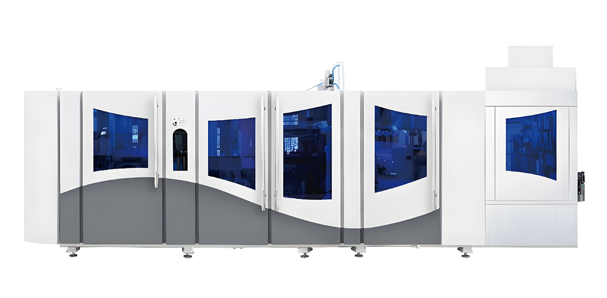
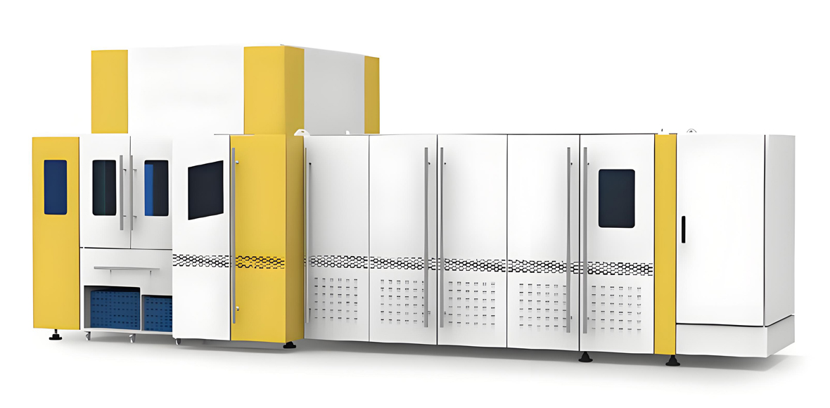
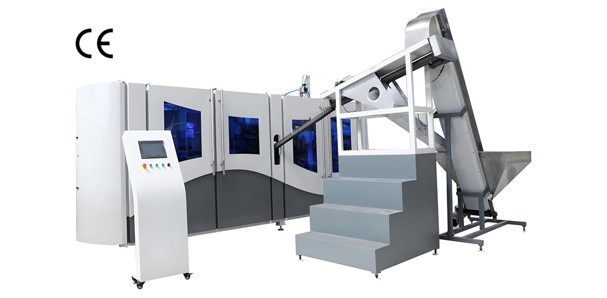
When the technical discussion reaches the question of which machine actually forms the bottle, output volume becomes the deciding factor. For producers running long, stable campaigns of a single bottle family — hot-fill tea and juice, lactic acid drinks, water in 350 mL to 1.5 L formats — the FGX high-speed rotary series is the configuration YuDa builds for that duty.
The FGX series covers the 8,000 to 15,000 bottles per hour band, with a single-mold speed of 2,500 to 3,000 bottles per hour. That per-cavity figure is the number worth studying: it means output scales cleanly with cavity count rather than depending on unusually aggressive settings, and it means a given output target can be met with fewer cavities than a slower architecture requires. Fewer cavities means fewer mold sets to buy, fewer sets to change and fewer sets to maintain.
Three design features underpin that speed. The first is the cam-linked motion system, which integrates mold opening, mold locking and bottom mold elevation into a single coordinated movement instead of three independently timed mechanisms. This removes the sequencing gaps that limit conventional designs and reduces wear points. The second is the high-speed servo drive system, which gives precise, repeatable stretch rod motion and clamp timing at rotary speeds. The third is the energy-saving oven, in which the heater distance is minimized to 38.1 mm; bringing the lamps closer to the preform surface improves radiative coupling and saves more than 30 percent of heating electricity compared with conventional heating ovens. Since the oven is the largest electrical load on the line, that is a structural saving rather than a marginal one.
The series is also built for supervision at a distance. A remote monitoring system lets engineers at the China headquarters read PLC data from a mobile device, review alarm history and abnormal trends, and feed findings back to the customer’s site. For an exporter operating in a country with no local service depot, that capability shortens diagnosis from days to hours.
| Parameter | FGX 4-Cavity | FGX 6-Cavity | FGX 8-Cavity |
|---|---|---|---|
| Architecture | Rotary, continuous motion | Rotary, continuous motion | Rotary, continuous motion |
| Cavities | 4 | 6 | 8 |
| Single-mold speed | 2,500 to 3,000 bph | 2,500 to 3,000 bph | 2,500 to 3,000 bph |
| Rated output, cold fill | Up to about 10,000 bph | Up to about 14,000 bph | Up to about 15,000 bph and above |
| Rated output, heat set | About 6,000 to 7,000 bph | About 8,500 to 10,000 bph | About 11,000 to 13,000 bph |
| Container volume range | 200 mL to 1.5 L | 200 mL to 1.5 L | 200 mL to 1.0 L |
| Maximum bottle diameter | About 95 mm | About 95 mm | About 85 mm |
| Maximum bottle height | About 320 mm | About 320 mm | About 300 mm |
| Neck finish range | 28 mm to 38 mm | 28 mm to 38 mm | 28 mm to 38 mm |
| Pre-blow pressure | 8 to 16 bar | 8 to 16 bar | 8 to 16 bar |
| Final blow pressure | 30 to 40 bar | 30 to 40 bar | 30 to 40 bar |
| Oven heater distance | 38.1 mm energy-saving layout | 38.1 mm energy-saving layout | 38.1 mm energy-saving layout |
| Heat-set option | Available with oil temperature controller | Available with oil temperature controller | Available with oil temperature controller |
| Control | PLC with touch screen, recipe management, remote monitoring | PLC with touch screen, recipe management, remote monitoring | PLC with touch screen, recipe management, remote monitoring |
Figures above are indicative configuration bands for planning. Final specifications — installed power, air consumption, cavity layout and mold data — are confirmed against the customer’s bottle drawing, fill temperature and target rate, because a deep-panel hot-fill bottle and a smooth water bottle of the same nominal volume produce materially different numbers.
YuDa Full Automatic Standard-Speed Series
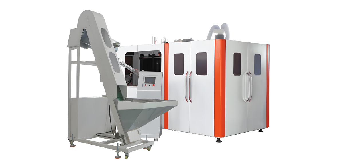
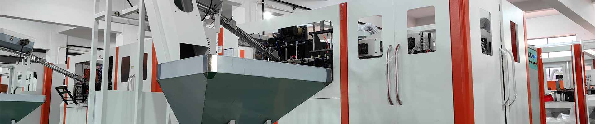
Most vacuum bottle and daily use bottle programs do not need 15,000 bottles per hour. They need 2,000 to 7,000 bottles per hour across several bottle shapes, with fast changeover and the ability to handle wide mouths, deep panels and irregular cross sections. That is the territory of the YuDa full automatic standard-speed series, covering 1,000 to 7,000 bottles per hour in a linear architecture.
The linear layout is the right answer for this duty for structural reasons rather than commercial ones. Each mold station completes its full cycle in place, so the heat-set dwell can be extended without redesigning the machine’s motion. Mold sets are simpler and less costly, so a converter running eight or ten bottle codes can afford tooling for all of them. And the machine tolerates containers that a rotary carousel would reject — 45 to 63 mm wide-mouth jars for sauces and creams, oval and flat-sided detergent bottles, handled containers and tall edible oil bottles.
The series carries the same advanced heating system and energy-saving philosophy as the high-speed machines, along with a modular construction that keeps maintenance and changeover economical. Modularity matters practically: heating modules, clamp modules and transfer modules can be serviced or replaced as units, so a fault does not immobilize the whole machine while a technician works through a monolithic assembly.
| Parameter | 2-Cavity Configuration | 4-Cavity Configuration | 6-Cavity Configuration | Large-Volume Configuration |
|---|---|---|---|---|
| Architecture | Linear, full automatic | Linear, full automatic | Linear, full automatic | Linear, full automatic |
| Cavities | 2 | 4 | 6 | 1 or 2 |
| Rated output, cold fill | 1,800 to 2,600 bph | 3,600 to 5,200 bph | 5,400 to 7,000 bph | 700 to 1,400 bph |
| Rated output, heat set | 1,100 to 1,700 bph | 2,200 to 3,300 bph | 3,300 to 4,500 bph | 450 to 900 bph |
| Container volume range | 50 mL to 2.0 L | 50 mL to 2.0 L | 50 mL to 1.5 L | 2.0 L to 10 L |
| Maximum bottle diameter | About 110 mm | About 105 mm | About 95 mm | About 230 mm |
| Maximum bottle height | About 340 mm | About 340 mm | About 320 mm | About 450 mm |
| Neck finish range | 18 mm to 63 mm wide mouth | 18 mm to 45 mm | 24 mm to 38 mm | 28 mm to 100 mm |
| Clamping force per station | Approximately 60 to 90 kN | Approximately 80 to 130 kN | Approximately 100 to 150 kN | Approximately 150 to 220 kN |
| Indicative installed power | 28 to 45 kW | 50 to 80 kW | 75 to 110 kW | 60 to 100 kW |
| High-pressure air demand | 0.3 to 0.5 m3/min | 0.6 to 1.0 m3/min | 0.9 to 1.5 m3/min | 0.8 to 1.6 m3/min |
| Heat-set option | Available | Available | Available | Available |
| Typical products | Cosmetic, sauce jar, small daily chemical | Juice, tea, detergent, shampoo | Beverage, lactic acid drink, water | Edible oil, bulk detergent, chemical drum |
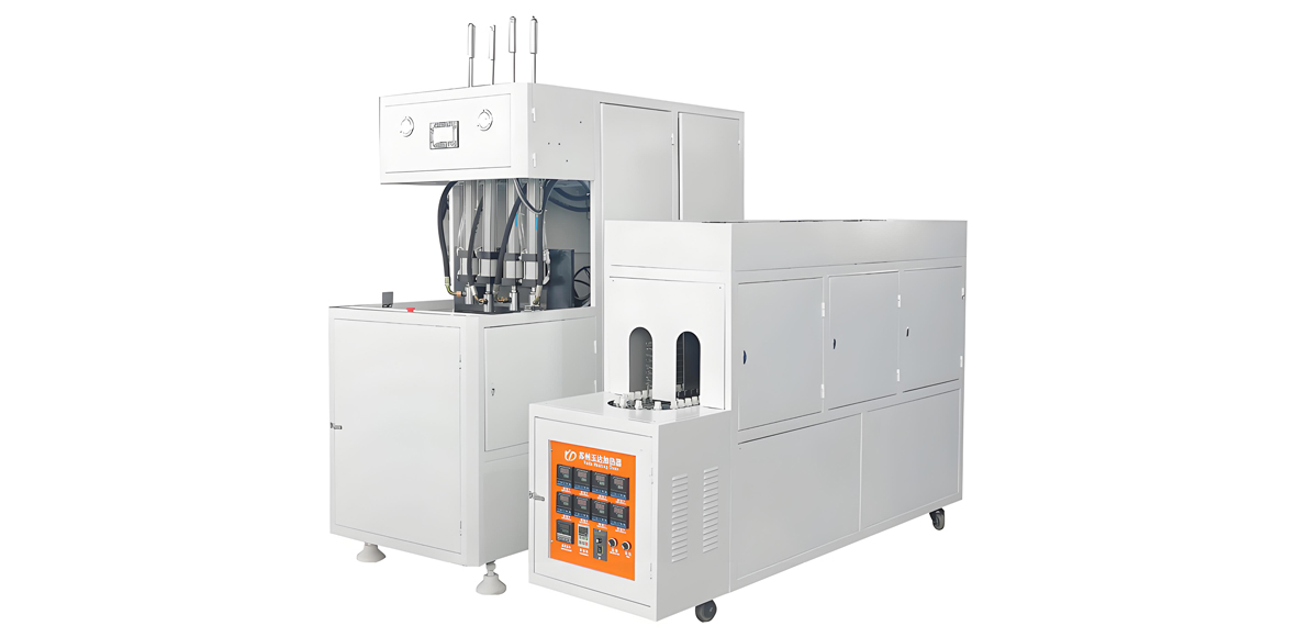
For producers with limited plant area or with a water and simple-beverage focus, YuDa also builds the linear blowing-filling-capping CombiBlock and full bottle blow-filling-capping machines, which form the bottle, fill it and apply the closure in one continuous process. Removing the air conveyor and intermediate handling saves floor area and eliminates a contamination path. For the semi-automatic route — where a separate preform heating machine feeds a manually loaded blowing station — YuDa maintains a semi-auto series with lower procurement cost and short lead time, which is the usual choice for very small runs, specialty containers and sampling work rather than for a continuous vacuum bottle program.
Heat-Set Configuration Options
Heat setting is specified as a package rather than as a checkbox, and the package differs by how hot the product will be filled. The table below sets out what has to be added to a base machine at each level, which is the practical form of the question most buyers actually ask.
| Configuration Level | Fill Temperature Covered | Added Equipment | Effect on Output | Relative Investment Level |
|---|---|---|---|---|
| Standard cold fill | Ambient to 50 degrees Celsius | Chilled water mold circuits only | Baseline | Low |
| Warm fill | 60 to 75 degrees Celsius | Warm water mold circuit, extended oven soak | Minus 10 to 15 percent | Low to Medium |
| Standard heat set | 80 to 88 degrees Celsius | Oil temperature controller, heat-set mold set, separately cooled base insert, reinforced neck cooling, extended oven zoning | Minus 30 to 40 percent | Medium to High |
| High-temperature heat set | 88 to 95 degrees Celsius | All of the above plus crystallized-neck preforms, dual-circuit mold thermal control, internal bottle cooling before ejection | Minus 40 to 50 percent | High |
| Heat set plus in-bottle pasteurization | Above 92 degrees Celsius with hold | All of the above plus validated closure system and reinforced base design | Minus 45 to 55 percent | Very High |
Two planning lessons follow from this table. First, decide the maximum fill temperature the plant will ever need before ordering the machine, because a machine specified for heat setting can always run cold-fill products by switching mold circuits, while retrofitting heat setting onto a machine that was never designed for it is difficult and often uneconomic. Second, size the machine on the heat-set output figure, not the cold-fill figure, if hot fill is the main business — a line bought on its cold-fill nameplate will disappoint the moment the oil temperature controller is switched on.
Application Industries and End Products
The equipment set described here serves two broad families that share a workshop more often than outsiders expect: hot-filled food and beverage containers, and ambient-filled daily use and household chemical containers.
Hot-Fill Beverages
Ready-to-drink tea, fruit juice and juice drinks, herbal and functional beverages, sports and isotonic drinks, and coffee-based drinks are all filled hot to achieve commercial sterility without aseptic infrastructure. These products use 350 mL to 1.5 L bottles with 38 mm wide necks or 28 mm PCO finishes, four to eight vacuum panels, crystallized necks above 88 degrees Celsius, and heat-set molds at 135 to 155 degrees Celsius. Clarity and panel definition are commercially important because the bottle is the primary shelf communication.
Lactic Acid and Dairy-Type Drinks
Fermented milk drinks and lactic acid beverages are typically filled warm or hot and are highly sensitive to oxygen and to flavor scalping. Bottle sizes are small — 100 mL to 500 mL — often in multi-packs, with tight neck tolerances for foil sealing. High cavity counts and short cycles matter here, and the neck finish frequently has to accommodate an induction seal as well as a cap.
Sauces, Condiments and Wide-Mouth Food
Ketchup, chili and soy sauces, salad dressings, jams and pickles use 45 to 63 mm wide-mouth PET jars and bottles, filled hot and often pasteurized. These are the most demanding containers on the list: heavy preforms, long soak times, deep panels, high top load for stacking, and neck finishes at the upper size limit. A linear machine with extended dwell and strong clamping is usually the right architecture.
Detergents, Household and Daily Chemical Products
Laundry detergent, fabric softener, dishwashing liquid, surface cleaners, disinfectants and bleach-adjacent formulations are filled at ambient temperature into 200 mL to 5 L containers. The technical demands shift from thermal stability to chemical compatibility, top load for pallet stacking, ergonomics — handles, grip waists, flat sides for labeling — and squeeze behavior for dispensing. Vacuum panels are unnecessary, but ribbing for stiffness is common, and wall distribution still governs whether a tall bottle survives a full pallet.
Edible Oil
Cooking oil bottles from 500 mL to 5 L are ambient filled but structurally demanding because of their height-to-diameter ratio and the weight of the contents. Preform weights run high, stretch ratios are moderated to avoid over-thinning the sidewall, and the base needs strong support to resist rocking. Clarity is a selling point, so pearlescence control in the oven is a live process concern.
Personal Care and Cosmetics
Shampoo, conditioner, body wash, lotion, toner and serum bottles run from 50 mL to 1 L. This segment cares most about surface finish, shape complexity, wall uniformity in decorative regions and compatibility with pumps and airless closures. Small cavity counts with excellent mold surface quality and fine oven zoning beat raw speed, which is why a two- or four-cavity linear machine is the common choice.
Requirement to Model Selection Guide
The following table converts a production requirement into a concrete machine configuration. It is intended as a planning shortcut; the final configuration is always confirmed against the bottle drawing, because panel depth, neck size and height-to-diameter ratio can move a project one row in either direction.
| Target Output | Volume Range | Hot Fill Required | Recommended YuDa Machine | Cavities | Heat-Set Package |
|---|---|---|---|---|---|
| Up to 1,200 bph | 50 mL to 1.0 L cosmetic and specialty | No | Semi-auto series | 1 to 2 | Not required |
| 1,500 to 2,500 bph | 100 mL to 2.0 L daily chemical | No | Full automatic standard-speed series | 2 | Not required |
| 1,500 to 2,500 bph | 350 mL to 1.0 L juice or tea | Yes, 85 to 90 degrees Celsius | Full automatic standard-speed series | 4 | Standard heat set |
| 3,000 to 5,000 bph | 350 mL to 1.5 L beverage | No | Full automatic standard-speed series | 4 | Not required |
| 3,000 to 4,500 bph | 350 mL to 1.0 L hot-fill tea | Yes, 88 to 92 degrees Celsius | Full automatic standard-speed series | 6 | High-temperature heat set with crystallized neck |
| 5,000 to 7,000 bph | 500 mL water or lactic drink | No or warm fill | Full automatic standard-speed series | 6 | Warm fill package if needed |
| 8,000 to 10,000 bph | 350 mL to 600 mL beverage | No | FGX high-speed series | 4 | Not required |
| 8,000 to 10,000 bph | 350 mL to 600 mL hot-fill juice | Yes, 85 to 92 degrees Celsius | FGX high-speed series | 6 | High-temperature heat set |
| 12,000 to 15,000 bph | 350 mL to 600 mL water or CSD | No | FGX high-speed series | 8 | Not required |
| 700 to 1,400 bph | 2.0 L to 10 L edible oil or bulk chemical | No | Large-volume linear configuration | 1 to 2 | Not required |
| 1,000 to 2,000 bph | 45 to 63 mm wide-mouth sauce jar | Yes, with pasteurization | Full automatic standard-speed series, wide-mouth build | 2 to 4 | Heat set plus pasteurization package |
| 2,000 to 6,000 bph | 250 mL to 2.0 L water, integrated filling | No | Linear CombiBlock or BFC machine | 2 to 6 | Not required |
Common Defects and Corrective Actions
Most defects on a PET vacuum bottle line are thermal or distributional in origin, which means the correct response is usually an adjustment upstream of where the symptom appears. The table below organizes the recurring problems by root cause rather than by appearance, since two very different-looking defects often share one cause.
| Defect | Appearance | Probable Causes | Corrective Actions |
|---|---|---|---|
| Pearlescence / stress whitening | Hazy milky zones, often in the base or lower body | Preform too cold in that zone; stretch ratio beyond the natural limit; pre-blow too early; resin over-dried or degraded | Raise the affected oven zone by 2 to 4 degrees Celsius; delay pre-blow slightly; check the stretch ratio against the 9 to 14 planar window; verify dryer temperature is not above 170 degrees Celsius |
| Uneven wall thickness | Thin and thick sides, measurable ovality | Preform not rotating in the oven; one lamp bank failed; uneven neck shielding; mold temperature imbalance | Inspect rotation on every mandrel; test lamp continuity zone by zone; clean reflectors; verify equal flow through both mold halves |
| Base stress cracking after storage | Radial or ring cracks at the base weeks after production | Under-stretched, thick amorphous base; raised or crystalline gate vestige; base cooled too fast leaving residual stress; contact with alkaline cleaning residue | Reduce base material by trimming preform weight or adjusting pre-blow timing; improve gate quality on the preform tool; moderate base cooling; run a stress crack test on the current base design |
| Vacuum panels do not recover | Panels stay dented after the pack cools | Insufficient heat setting so stress relaxes at fill temperature; panel too deep for the available wall thickness; preform too light; cooling of the filled pack too rapid | Raise mold temperature toward 150 degrees Celsius and extend the dwell; increase preform weight by 2 to 4 g; reduce panel depth in the mold; slow the pack cooling profile |
| Bottle shrinks or distorts after hot fill | Reduced height, wavy sidewall, label wrinkling | Heat setting incomplete; dwell too short; mold surface temperature below target; oven exit temperature too low for crystallization | Verify mold surface with a contact thermometer rather than relying on the setpoint; extend the dwell in 0.5 s steps; raise oven exit temperature to the 105 to 115 degrees Celsius band; run a thermal stability test at each change |
| Neck deformation or ovality | Threads out of round, capping leaks, support ring warped | Neck shielding inadequate; shield cooling water flow low; oven set too high overall; neck not crystallized for the fill temperature | Check shield cooling circuit and flow; lower the top oven zone; add crystallized-neck preforms for fills above 88 degrees Celsius |
| High acetaldehyde / off-taste | Faint fruity odor, sensory panel rejection | Melt over-heated during preform injection; local overheating in the reheat oven; excessive residence time in the hot runner | Lower melt temperature and check hot runner zone control; reduce oven peak zones and lengthen soak instead; verify resin lot and drying temperature |
| Poor panel and rib definition | Soft, rounded panel corners | Final blow pressure too low; blow air flow restricted; preform too cold; mold venting inadequate | Raise final blow toward 38 to 40 bar; check valve and line sizing and receiver pressure at the moment of blow; raise body zone temperature; clean and verify mold vents |
| Flash at the parting line | Thin fin along the mold split | Clamping force insufficient for the blow pressure and projected area; mold face damaged or contaminated; blow pressure too high | Verify clamping setting and toggle condition; clean and inspect mold faces; reduce final blow to the minimum that still fills the detail |
| Thin or off-center base | Base wall below specification, gate off-axis | Stretch rod too slow or mistimed; pre-blow too early; preform not centered in the mold | Increase stretch rod speed toward 1.4 m/s; delay pre-blow by 10 to 20 ms; check gripper and centering alignment |
| Black specks or contamination | Dark points visible in the wall | Degraded material in the hot runner; preform dust; ambient contamination in the preform hopper | Purge and inspect the hot runner; add an air rinse before the oven; cover preform storage and control workshop dust |
| Low top load | Bottle collapses under stacking | Shoulder too thin; under-orientation; heat setting relaxed the structure without compensating weight | Shift material to the shoulder with earlier pre-blow; raise preform weight; verify planar stretch ratio is inside the effective window |
Utilities, Workshop Layout and Installed Load
A complete line is a utility project as much as an equipment project, and utility planning is where new entrants most often under-budget. The table below gives planning-level figures for three representative line sizes, covering the blow molding hall itself; a filling and packing hall adds its own load.
| Utility Item | Small Line, About 2,000 bph | Medium Line, About 6,000 bph | High-Speed Line, About 12,000 bph |
|---|---|---|---|
| Blow molding machine installed power | 28 to 45 kW | 75 to 110 kW | 140 to 200 kW |
| High-pressure compressor power | 30 to 45 kW | 75 to 110 kW | 160 to 250 kW |
| Low-pressure compressor power | 7.5 to 15 kW | 22 to 37 kW | 45 to 75 kW |
| Chiller power | 10 to 18 kW | 30 to 50 kW | 60 to 100 kW |
| Oil temperature controller, heat-set builds | 12 to 24 kW | 24 to 48 kW | 48 to 96 kW |
| Auxiliary equipment, conveyors and lighting | 8 to 15 kW | 20 to 35 kW | 40 to 60 kW |
| Indicative total connected load | 95 to 160 kW | 250 to 390 kW | 500 to 780 kW |
| Typical demand factor | 0.6 to 0.7 | 0.6 to 0.7 | 0.65 to 0.75 |
| Cooling water circulation | 8 to 15 m3/h | 25 to 40 m3/h | 50 to 80 m3/h |
| Compressed air, high pressure | 0.3 to 0.6 m3/min | 0.9 to 1.5 m3/min | 1.6 to 2.5 m3/min |
| Compressed air, low pressure | 0.6 to 1.0 m3/min | 1.5 to 2.5 m3/min | 3.0 to 4.5 m3/min |
| Blowing hall floor area | 120 to 200 m2 | 250 to 400 m2 | 450 to 700 m2 |
| Recommended ceiling height | 4.5 m minimum | 5.0 m minimum | 6.0 m minimum |
| Operators per shift, blowing only | 1 to 2 | 2 to 3 | 3 to 4 |
Beyond the numbers, four layout principles repay attention. Keep the compressor room separate and acoustically treated, with generous ventilation, and site it close to the blower to minimize high-pressure pipe runs and the pressure drop they cause. Put preform storage adjacent to the unscrambler, on pallets off the floor, in a covered and reasonably dry area — preforms that sit in a humid yard arrive at the oven with different moisture and behave differently. Route the air conveyor with the shortest practical path and no unnecessary elevation changes. And provide a genuine maintenance aisle around the blower; molds are heavy, changeovers happen at inconvenient hours, and a machine that can only be accessed from one side doubles every changeover.
Air cleanliness in the hall itself matters for food contact production. A positive-pressure blowing hall with filtered make-up air, smooth washable surfaces and controlled personnel access is the practical minimum for beverage work. Full cleanroom classification is rarely necessary for the blowing operation, but the area around the air rinse and the transfer to the filler deserves localized protection.
Service, Testing and Support
A full line is a multi-year relationship, not a single transaction, and the support structure around the equipment usually determines whether the project reaches its nameplate output. YuDa’s approach follows the shared Wanplas service framework, applied to the specifics of PET bottle production.
Bottle Development and Sample Trials
Every project starts with the container, not the machine. Customers send a bottle drawing, a sample, or simply a description of the product, the fill temperature and the target output, and the engineering discussion works backward from there to preform weight, stretch ratios, cavity count, panel design and heat-set requirement. Where a new bottle shape is involved, a trial mold and sample run establish that the geometry is producible before the full tooling package is committed. This step is the cheapest insurance available on a hot-fill program, because a panel design that cannot be reliably formed will otherwise be discovered after the whole line is installed.
Factory Acceptance Testing Before Shipment
Machines are assembled, run and tested at the factory before shipment, using the customer’s own molds and preforms wherever possible. A factory acceptance test verifies output rate at the agreed cycle, bottle weight consistency across cavities, wall distribution against the drawing, and — on heat-set builds — thermal stability of the finished bottle at the intended fill temperature. Customers are welcome to attend; the open factory policy shared across Wanplas means a buyer can walk the assembly floor, watch the machine run and take sample bottles away for their own testing before releasing the shipment.
Installation, Commissioning and Training
Engineers travel to site for installation and commissioning, covering mechanical setup, utility connection verification, first-article production and process optimization on the customer’s actual resin and ambient conditions. Training runs alongside commissioning and covers three separate audiences: operators, who need setup, changeover and routine checks; maintenance technicians, who need lubrication schedules, wear part replacement and fault codes; and quality staff, who need the test routine described earlier in this article. Training that stops at the operator level is the most common reason a line’s performance decays in its second year.
Spare Parts and Wear Items
The Wanplas brand policy provides USD 500 in free parts every year, plus free replacement of parts that fail within the warranty period. The parts that actually matter on a PET line are predictable: quartz heating lamps, stretch rod seals and bushings, blow valve seals, gripper pads and springs, mold vents and parting line inserts, drive belts, filter elements for the air treatment train, and desiccant for the dryer. A sensible commissioning kit covers a full set of lamps for one oven, two changes of seals, and a year of filter elements. Molds and change parts for additional bottle codes are quoted separately, and it is worth ordering the second bottle code’s tooling with the machine rather than later, since tooling lead time is usually the constraint on launching a new SKU.
Remote Monitoring and Ongoing Support
The remote monitoring system allows engineers at the China headquarters to read PLC data from the installed machine, review alarms and trends, and advise the site team directly. In practice, most process questions — a drifting oven profile, an intermittent gripper fault, an unexplained rise in reject rate — can be diagnosed from the data before anyone books a flight. For customers in the 60-plus countries YuDa serves, that shortens the resolution cycle dramatically and keeps a production problem from becoming a production stoppage.
| Stage | Customer Provides | YuDa Provides | Output of the Stage |
|---|---|---|---|
| Enquiry and definition | Bottle drawing or sample, fill temperature, target output, resin type | Feasibility review, preform weight proposal, machine configuration | Agreed technical specification |
| Bottle and mold design | Approval of bottle geometry and neck finish | Mold design, stretch ratio verification, panel layout review | Released mold drawings |
| Sample trial | Preforms or preform specification | Trial run, sample bottles, test data | Validated bottle design |
| Manufacture | Voltage, frequency, local standards | Machine build, component sourcing, quality control | Completed machine |
| Factory acceptance test | Optional attendance, sample preforms | Run test, output and quality verification, documentation | Signed acceptance record |
| Shipment | Site readiness, utility installation | Packing, loading, transportation guarantee | Equipment on site |
| Installation and commissioning | Utilities connected, operators available | On-site engineers, setup, process optimization | Line producing to specification |
| Training | Operator, maintenance and quality staff | Structured training across all three roles | Self-sufficient plant team |
| Ongoing operation | Production data, maintenance records | Remote monitoring, USD 500 free parts per year, warranty replacement, technical support | Sustained output and quality |
Frequently Asked Questions
What is the difference between a PET vacuum bottle and an ordinary PET bottle?
A PET vacuum bottle is engineered to absorb the negative internal pressure created when hot-filled product cools and contracts inside a sealed container. It carries vacuum absorbing panels or reinforcing ribs in the sidewall, or a controlled-inversion base, and it is produced with heat-set molds at 120 to 160 degrees Celsius so that the bottle stays dimensionally stable above the glass transition temperature. An ordinary cold-fill bottle experiences no meaningful negative pressure, needs no panels, and is blown into a chilled mold at 8 to 15 degrees Celsius with a much shorter cycle and a lighter preform.
Can I convert my existing cold-fill blow molding machine to produce hot-fill vacuum bottles?
Sometimes, but rarely well. Conversion requires heat-set molds, an oil temperature controller, additional oven zoning and soak length, reinforced neck cooling, and often crystallized-neck preforms. If the base machine was not designed with the clamp rigidity, thermal isolation and cycle flexibility for heat setting, the result is a machine that technically produces hot-fill bottles but at low output with unstable quality. The economic answer is usually to specify heat-set capability when the machine is bought, since a heat-set machine can always run cold-fill products but not the reverse.
How many vacuum panels should a 1 L hot-fill bottle have?
Six to eight panels is the usual starting point for 1 L, bounded top and bottom by continuous horizontal ribs that define the label mounting surface. The exact number depends on the vacuum volume to be absorbed, which follows from the fill temperature and the headspace, and on the brand’s visual preference. More, shallower panels distribute strain and look cleaner; fewer, deeper panels absorb more volume but are visually prominent and more likely to buckle asymmetrically. The design should always be verified with a physical fill-and-cool test rather than accepted from calculation alone.
What output should I expect if I switch a machine from cold fill to heat set?
Plan on losing roughly 35 to 45 percent of the cold-fill rate for a standard heat-set program, and up to 50 percent for high-temperature heat setting with in-bottle pasteurization. The loss is the heat-set dwell — the time the bottle spends held against the hot mold for crystallization to develop. This is why a plant with a hot-fill business should size the machine on its heat-set output figure, and why an increase in cavity count is often more economical than an attempt to shorten the dwell.
Is a high-pressure air recovery system worth installing on a small line?
Usually yes if the line runs more than one shift. Compressed air is the dominant energy consumer in a PET bottle plant, and recovery typically returns a meaningful share of blowing air to the low-pressure network, commonly reported in the range of 20 to 35 percent depending on bottle volume and cycle time. The relative investment level is Low to Medium and the payback improves with running hours, bottle size and electricity tariff. On single-shift operations with small bottles the case is weaker but still worth calculating.
Do I need to injection mold my own preforms, or can I buy them?
Both routes work. Buying preforms reduces capital intensity, shortens time to first production and avoids the complexity of a second molding process, which suits a producer starting out or running modest volumes. Molding in-house gives control over weight, resin selection, neck crystallization and preform freshness, and generally reduces per-bottle material cost at higher volumes. Many producers start by buying and integrate preform injection once volume justifies it; Wanplas supplies matched preform injection systems for that step so the two stages are configured against one bottle drawing.
Why do my bottles look fine at production but crack in the warehouse weeks later?
That pattern is the signature of environmental stress cracking in the base. The base is the thickest, least oriented and last-quenched region of the bottle, so it retains residual stress. If the base is over-thick and under-stretched, if the injection gate leaves a raised or crystalline vestige, or if the base is quenched too aggressively, stress concentrates at the gate area and cracks propagate over time, often accelerated by contact with alkaline cleaning residues. The remedies are on the preform and base design side: better gate quality, less base material, moderated base cooling and a documented stress crack test on any new base geometry.
What resin intrinsic viscosity should I specify for hot-fill vacuum bottles?
Bottle-grade PET in the 0.80 to 0.85 dL/g range is the normal choice for hot-fill and heavier containers, compared with 0.76 to 0.82 dL/g for standard water and ambient-fill bottles. Higher intrinsic viscosity gives better melt strength during preform injection, better stress crack resistance in the finished base, and more forgiving behavior at the higher processing temperatures heat setting requires. The trade-off is a slightly narrower drying and injection window, which makes the dryer specification even more important.
How long does a mold changeover take, and how can it be reduced?
On a linear machine, a full mold change for a different bottle code typically takes one to three hours depending on cavity count and whether the neck finish also changes; on a rotary machine it takes longer because every station must be changed. Changeover time is reduced by quick-release mold mounting, pre-heated spare mold sets staged beside the machine, a written changeover sequence with defined roles, and by keeping a stock of neck-specific change parts for the unscrambler and transfer so that rail adjustment does not become trial and error. Recipe management in the control system, storing all process parameters per bottle code, removes the re-tuning phase that otherwise follows every change.
What should be tested before a hot-fill bottle design is released to production?
At minimum: thermal stability by filling with water at the intended temperature, capping, cooling and measuring volume and dimensional change; vacuum panel recovery after full cool-down; top load at the pallet stacking height; burst pressure with margin over the maximum expected internal pressure; wall thickness at the defined measurement points; neck dimensions against the finish standard; and stress crack resistance on the base. Those seven tests, documented on the actual production line rather than on a laboratory sample, form the validation package that most brand owners will ask to see.
Conclusion
A PET vacuum bottle line and a PET daily use bottle line are built from the same ten stations, but the specification of every station shifts once the product is filled hot. The dryer must reach lower moisture. The preform gets heavier and often needs a crystallized neck. The oven needs more zones and a longer soak. The blow machine needs clamping rigidity and precise timing to reproduce panel detail. The mold runs at 120 to 160 degrees Celsius on thermal oil rather than at 8 to 15 degrees Celsius on chilled water, and the cycle pays for that with a 35 to 45 percent reduction in per-cavity output. The air system, so often treated as a utility afterthought, becomes the largest single energy consumer and the most valuable place to invest in recovery. And the inspection program has to include thermal stability and panel recovery testing, because a bottle can pass every dimensional check and still collapse on the shelf.
The practical planning sequence follows from that. Fix the bottle first — volume, neck finish, panel count and depth, base structure, fill temperature. Derive preform weight and stretch ratios from the bottle. Choose the architecture from the output requirement and the SKU mix: linear where flexibility, wide mouths and large volumes matter, rotary where a single bottle family runs at high volume for long campaigns. Size the machine on the heat-set rate if hot fill is the business. Then build the utilities around the resulting numbers rather than discovering them after installation.
YuDa, a Wanplas factory with more than 20 years in PET bottle blow molding, exports to over 60 countries and more than 20 patents, builds both halves of that choice: the FGX high-speed rotary series for 8,000 to 15,000 bottles per hour with a single-mold speed of 2,500 to 3,000 bottles per hour and an energy-saving oven at 38.1 mm heater distance, and the full automatic standard-speed series from 1,000 to 7,000 bottles per hour for multi-SKU vacuum bottle, wide-mouth and daily chemical production, alongside semi-automatic machines and integrated blowing-filling-capping blocks. Where the project extends beyond the blowing hall — preform injection, tooling, scrap recovery and pelletizing — Wanplas supplies matched equipment so one configuration covers the whole chain.
If you are configuring a line for PET vacuum bottles, daily use bottles, or both on the same floor, send your bottle drawing or a physical sample, your intended fill temperature, your target output in bottles per hour and the SKU range you expect to run. With that information our engineers will propose a complete station-by-station configuration, calculate the preform weight and stretch ratios, size the air and cooling systems, and lay out the workshop footprint. We can run a sample trial on your bottle geometry before you commit to tooling, and you are welcome to visit the factory, watch your machine run its acceptance test and take sample bottles away for your own validation. Tell us what you need to fill, and we will tell you exactly what it takes to make the bottle.