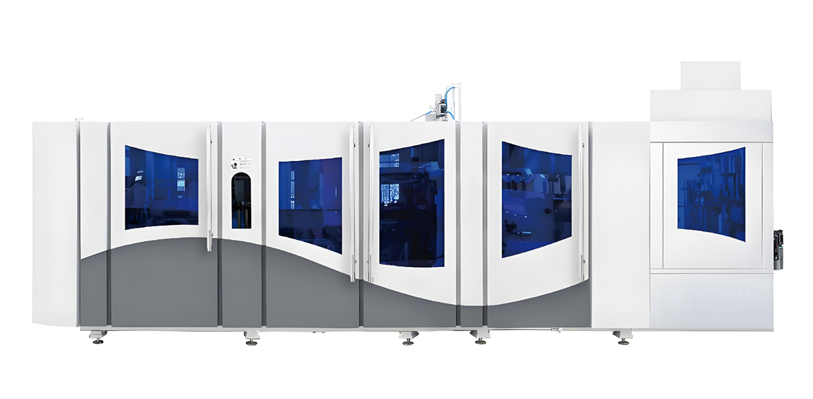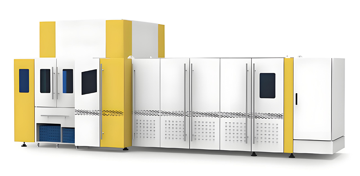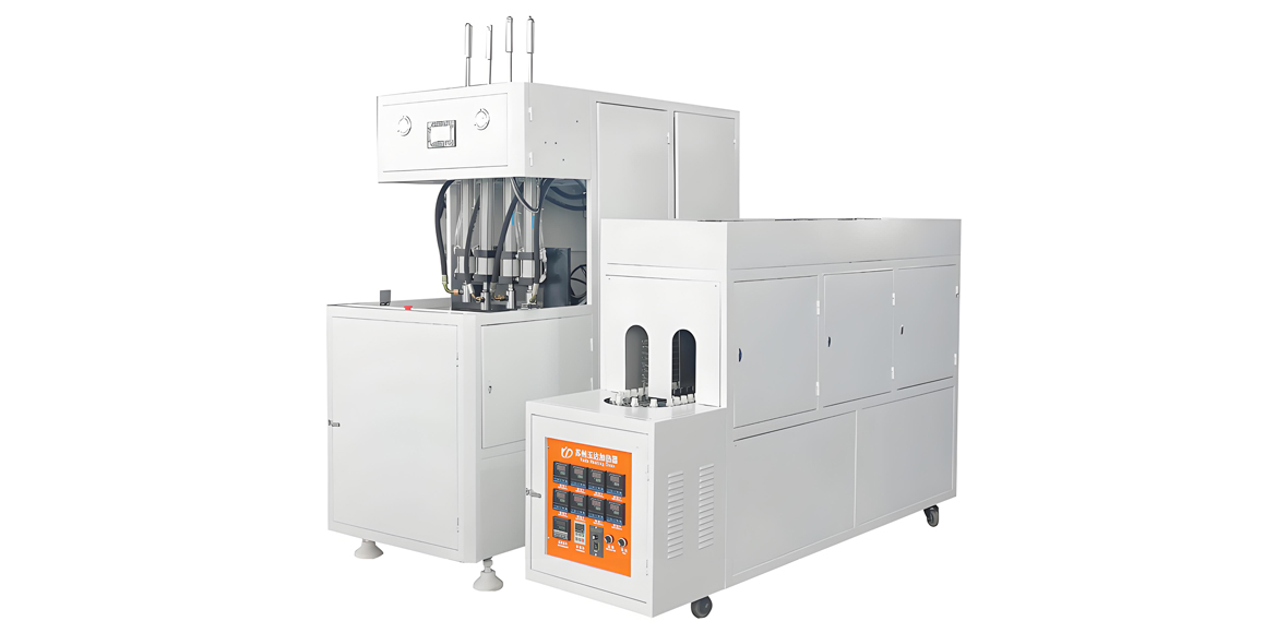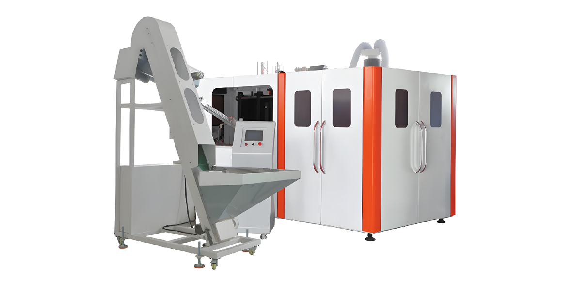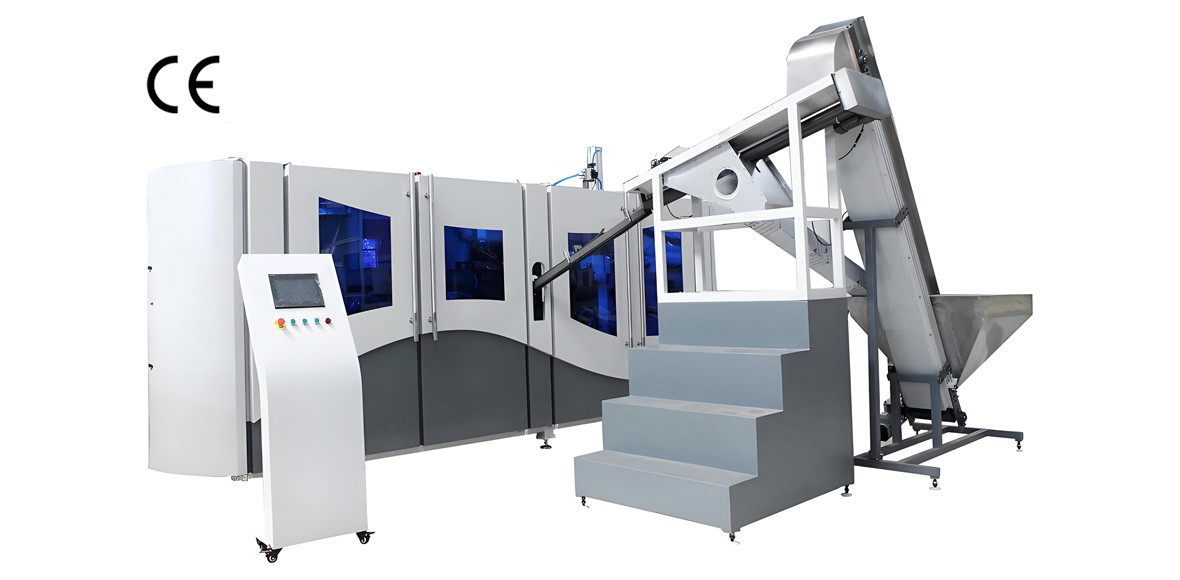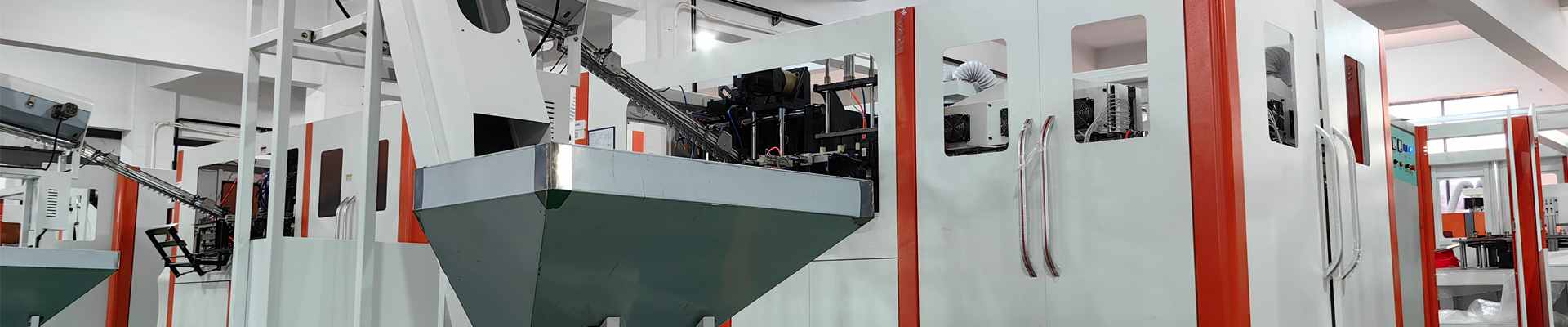
Mass beverage bottle production depends on high speed PET blow molding equipment that converts injection-molded preforms into finished bottles at tens of thousands of units per hour. A high speed PET flat blow molding machine, built on a linear or flat-bed layout, is the workhorse behind the bottled water, carbonated soft drink, edible oil, and ready-to-drink lines that fill retail shelves across more than sixty countries served by YuDa Machinery, a Wanplas factory and one of the top two PET bottle blow molding machine manufacturers in China with more than twenty years of experience and over twenty patents. This guide explains the architecture, heating, stretch blow process window, preform specification, bottle-type adaptability, quality assurance, stability design, combi-line integration, and efficiency metrics that determine whether a high speed PET stretch blow molding line meets the throughput, quality, and cost targets of a modern beverage plant. Whether you run a 3000 BPH startup line or a 72000 plus BPH mega-line, the engineering principles below apply directly to selection, commissioning, and daily optimization of PET blow molding machines and the beverage bottle production lines built around them.
Understanding High Speed PET Flat Blow Molding for Mass Beverage Production
High speed PET flat blow molding equipment refers to a linear-arranged stretch blow molding machine that takes heated PET preforms and forms them into bottles by combining mechanical stretching with pressurized air. The term flat describes the straight-line station layout, where preforms travel through a heating tunnel and then move to one or more blowing stations aligned in a row rather than on a rotating carousel. In the broader PET blow molding machine family, this linear or flat layout is contrasted with the rotary layout, where molds are mounted on a rotating wheel. Both deliver the biaxial orientation that gives PET bottles their clarity, strength, and drop resistance, but they serve different production scales and flexibility needs.
The core conversion happens through injection stretch blow molding, in which a preform is first reheated to a conditioning temperature, then axially stretched by a moving stretch rod while radial expansion is driven by compressed air. The combined biaxial orientation aligns PET molecules along two axes, raising tensile strength, improving barrier properties, and allowing thin, lightweight walls. A high speed machine repeats this cycle thousands of times per hour, so every subsystem from the infrared oven to the high-pressure valve block must be tuned for repeatability.
Mass beverage production sets unique demands. A bottled water plant may run a single 500 ml bottle shape for months, favoring maximum uptime and lowest energy per bottle. A contract packer serving multiple brands needs fast changeover between bottle shapes and gram weights. A carbonated soft drink line demands tighter pressure and base design to survive pasteurization and handling. A hot-fill line requires heat-set bottles that resist shrinkage at 85 to 92 degrees Celsius. A high speed PET flat blow molding machine must therefore be specified not only by rated BPH but by its process window, changeover time, energy per thousand bottles, and compatibility with downstream filling.
YuDa Machinery, a Wanplas factory specializing in PET bottle blow molding machines, positions its FGX high speed series and standard series around these demands. Key engineering choices include a unique cam linking system that integrates mold opening, mold locking, and bottom mold elevating into one movement, a high-speed servo driving system, a minimized heater pitch of 38.1 mm that saves more than 30 percent electricity versus conventional heating ovens, a modular design that simplifies maintenance and changeovers, and a remote monitoring system through which engineers at the China headquarters can read PLC data and feed abnormalities back to the customer site. These features illustrate the tradeoffs every buyer must weigh: speed, energy, stability, and flexibility.
Globally, the PET stretch blow molding equipment field includes established names such as Sidel, Krones, Sacmi, KHS, AOKI, and Nissei ASB alongside Chinese specialists like YuDa, Apollo, and Aibim within the Wanplas network. For mass beverage bottle production, the decision is rarely about a single machine but about a synchronized system: preform injection, reheating, blowing, filling, capping, labeling, and palletizing. The sections that follow break down each subsystem with concrete parameters so the reader can evaluate and specify with confidence.
Machine Architecture: Linear (Flat) vs Rotary Stretch Blow Molding
The single most consequential choice in a mass beverage project is the blow molder architecture. A linear or flat machine lays out blowing stations in a row and is favored for mid-range output and high flexibility; a rotary machine spins a carousel of molds and is favored for the highest output per floor area. Understanding the capacity envelope, single-cavity rate, cavity count, footprint, and changeover behavior of each is the foundation of correct sizing.
Capacity envelope and single-cavity rate
Linear stretch blow molding machines typically cover 3000 to 12000 BPH, while rotary machines scale from 12000 up to 72000 BPH and beyond on the largest carousels. The single-cavity output of a modern high speed machine falls between 1500 and 2400 BPH per cavity. Machine output is simply cavity count multiplied by single-cavity rate, so the same process physics governs both layouts; the difference is how many cavities can be packed and synchronized.
Cavity count and mold configuration
Common cavity numbers are 6, 8, 10, 12, 16, 20, and 24. Linear machines usually run 6 to 16 cavities, whereas rotary machines routinely use 12 to 24 or more. More cavities raise output but also raise the demand on heating uniformity, air supply, and mold clamping force. A 16-cavity linear machine at 2000 BPH per cavity yields about 32000 BPH, which already exceeds the top of the linear envelope in practice because of indexing limits, so very high outputs push toward rotary.
Footprint and changeover flexibility
Linear machines occupy a longer, narrower floor plan and are easier to service because each station is accessible from the side. They win on changeover flexibility: a mold set and heater recipe can be swapped in a shorter window, and small batch runs are economical. Rotary machines concentrate output into a compact footprint but require more disciplined changeover discipline and longer tooling setup, trading some flexibility for throughput density. The table below summarizes the comparison.
| Parameter | Linear (Flat) SBM | Rotary SBM |
|---|---|---|
| Typical output range | 3000 to 12000 BPH | 12000 to 72000 plus BPH |
| Single-cavity rate | 1500 to 2400 BPH per cavity | 1500 to 2400 BPH per cavity |
| Common cavity numbers | 6, 8, 10, 12, 16 | 12, 16, 20, 24 plus |
| Floor footprint | Long and narrow, Medium footprint per BPH | Compact per BPH, Very High density |
| Changeover flexibility | High, easier side access | Lower, higher tooling discipline |
| Best fit | Mid output, multi-SKU, contract packing | Single-SKU mega-lines, CSD, water |
| Investment level | Medium to High | High to Premium |
For a high speed PET flat blow molding machine, the linear layout remains attractive because it balances output with the ability to serve several bottle references on one line. YuDa’s FGX high speed series targets 8000 to 15000 BPH with single-mode speeds of 2500 to 3000 BPH, a range that fits many regional water and CSD plants. When the project exceeds 20000 BPH steadily on one bottle, a rotary machine or multiple linear machines in parallel should be evaluated, weighing the lower per-bottle energy of rotary against the redundancy and flexibility of parallel linear lines.
Clamping force of the blow mold is another architecture-sensitive parameter. Each cavity must be held closed against internal blow pressure without flash or parting-line marks. As cavity count and bottle size grow, the total clamping force requirement rises, and the mold clamping unit must distribute force evenly across all cavities. High speed linear machines use servo or hybrid clamp systems whose response time and repeatability directly affect cycle stability at the top of the speed range.
Two-Stage and One-Stage Processes with Preform Injection Matching
PET bottles are made by either a two-stage (two-step) process or a one-stage (one-step) process. In the two-stage process, preforms are injection molded on a separate injection molding machine, cooled, stored, and later reheated in the blow molder’s infrared oven before stretching and blowing. In the one-stage process, injection, conditioning, stretch blow, and ejection happen inside one integrated machine without the preform ever leaving the controlled thermal path. For mass beverage bottle production, the two-stage process dominates because it decouples preform making from blowing and lets a single blow molder run preforms from different injection batches.
Two-stage advantages for mass production
The two-stage process allows independent optimization of preform injection and bottle blowing. Preform injection molding machines run on longer cycles with multi-cavity preform molds, producing preforms at high yield with tight gram-weight and IV control. The blow molder then reheats only the surface layer of each preform to the conditioning window, which is more energy-efficient than melting the whole mass. Storage of preforms also buffers the line against injection downtime and enables preform sourcing from specialized suppliers.
One-stage advantages for specialty bottles
The one-stage process keeps the preform hot from injection to blowing, eliminating the reheat step and giving excellent wall distribution for wide-mouth, jars, and cosmetic bottles. It also reduces material handling and contamination risk. Its drawback for mass beverage production is lower flexibility and a tighter coupling between injection and blow output, so it is more common for pharmaceuticals, cosmetics, and small specialty runs than for 20000 plus BPH water lines. Wanplas’s Aibim factory specializes in injection blow molding and one-step machines for 3 ml to 1000 ml containers, a complementary capability within the same brand network.
Preform injection capacity matching
A balanced line matches preform injection output to blow output with a small buffer. The table below shows a representative matching logic. Preform output is governed by injection cycle time, cavity number of the preform mold, and gram weight. A blow molder at 24000 BPH consuming 24000 preforms per hour needs an injection cell that delivers at least that many preforms, typically with a 1.05 to 1.10 capacity margin so the blower is never starved.
| Blow molder output | Preforms per hour needed | Suggested injection capacity (with margin) | Typical preform mold cavities |
|---|---|---|---|
| 6000 BPH | 6000 | 6300 to 6600 | 48 to 72 |
| 12000 BPH | 12000 | 12600 to 13200 | 72 to 96 |
| 24000 BPH | 24000 | 25200 to 26400 | 96 to 144 |
| 48000 BPH | 48000 | 50400 to 52800 | Two injection cells or 144 plus |
Preform injection molding within the Wanplas ecosystem is supported by injection molding capability that pairs with YuDa blow molders, so a beverage producer can source preforms and blowing from one coordinated supplier network. For food and beverage contact, the preform resin and the finished bottle must meet FDA and EU 10/2011 food-contact requirements, and the injection process must avoid degradation that raises acetaldehyde and reduces IV.
Infrared Heating System: Oven Zones, Lamps, Neck Cooling, Temperature Window
The infrared oven is the heart of a two-stage PET blow molder. It must raise the preform wall to a uniform, controllable conditioning temperature while keeping the neck cool and stable. A high speed machine uses 8 to 12 heating zones, each with independently controlled lamp groups, and a total of 40 to 140 lamps depending on oven length and cavity count. The preform rotates as it travels so heating is circumferentially uniform, and reflector design focuses energy on the body while shielding the neck.
Zone layout and lamp count
More zones give finer control of the axial temperature profile, which matters because the preform wall is thick at the base and thin at the transition to the neck. The first zones warm the body gradually; later zones fine-tune the base and mid-body. Lamp count scales with oven length: a compact linear oven may carry 40 to 80 lamps, while a long high-cavity oven reaches 100 to 140. Each lamp is typically a short-wave or medium-wave infrared tube with adjustable percentage power, and groups are staged so the leading and trailing edges of the preform receive matched energy.
Preform rotation and neck protection
As the preform indexes through the oven, it spins on its mandrel at a controlled rotation rate so no side overheats. A neck cooling shield blows chilled air on the finish and neck ring, protecting thread geometry and preventing crystallization in the neck. Neck ring protection is essential because a deformed neck causes cap sealing failure and leak complaints downstream. The finish is held below roughly 60 degrees Celsius while the body reaches the working window.
Temperature window and uniformity
The preform surface is conditioned to 95 to 115 degrees Celsius. The inner-to-outer temperature differential should be 5 degrees Celsius or less so the wall stretches uniformly rather than splitting or webbing. NIR (near-infrared) lamps differ from conventional IR lamps in spectral match: NIR energy is absorbed more efficiently by PET, raising the working temperature faster and reducing oven length and power. Conventional IR ovens are mature and inexpensive but longer and less efficient per bottle. The table below compares the two heating philosophies.
| Attribute | Conventional IR oven | NIR oven |
|---|---|---|
| Spectral absorption in PET | Moderate | High, better matched |
| Oven length for same output | Longer | Shorter |
| Energy per thousand bottles | Higher | Lower |
| Capital level | Medium | High |
| Maturity and serviceability | Very High | High, growing |
Preheat time couples directly to throughput. A high speed line shortens dwell per preform, which raises lamp load and demands tighter control to keep the 95 to 115 degrees Celsius window. If preheat time is too short for the target temperature, the operator must raise lamp power, which raises energy and risks hot spots. If the oven is too long, floor space and capital grow. YuDa’s 38.1 mm heater pitch shortens the oven while keeping energy low, a design choice that directly improves the preheat-time versus capacity coupling on its FGX high speed series.
A practical rule for mass production: stabilize the oven recipe per preform gram weight and color, then hold it. Colorants and recycled content shift absorption, so a preform with higher masterbatch loading needs a different zone curve than a clear preform. In-line temperature sensing at the oven exit, combined with the remote monitoring system, lets engineers track drift and correct it before bottles degrade.
Stretch Blow Molding Process Window: Rod, Pre-Blow, High-Pressure, Ratios
Once the preform is conditioned, the blowing station executes a tightly timed sequence: the preform is clamped in the blow mold, the stretch rod descends, pre-blow air expands the parison slightly, high-pressure air forces the wall against the mold, and the bottle is vented and ejected. Each parameter has a window, and the window narrows as speed rises.
Stretch rod speed and timing
The stretch rod moves at 1.0 to 1.6 m/s, pulling the preform axially while the air expands it radially. Rod speed sets the axial stretch ratio and helps control material distribution at the base and shoulder. Too slow and the pre-blow hits before the rod reaches the base, causing thin spots; too fast and the rod can mark the base. Synchronization between rod position and pre-blow start is the single most important timing relationship in the cycle.
Pre-blow and high-pressure blow
Pre-blow uses 8 to 16 bar, started at 0.10 to 0.25 seconds after the rod begins, to gently open the parison and lay material into the mold before the high-pressure stage. High-pressure blow then uses 30 to 40 bar to fully form the bottle and imprint the mold surface, including the base petaloid shape and any embossing. Blow hold time is 0.15 to 0.5 seconds, after which the cavity is vented (exhaust time) so the bottle can release without sticking. The table below lists the typical window.
| Parameter | Typical window | Effect if off-window |
|---|---|---|
| Stretch rod speed | 1.0 to 1.6 m/s | Base mark, uneven wall |
| Pre-blow pressure | 8 to 16 bar | Webbing, poor base formation |
| Pre-blow start delay | 0.10 to 0.25 s after rod start | Thin base or folding |
| High-pressure blow | 30 to 40 bar | Unfilled corners, low stiffness |
| Blow hold time | 0.15 to 0.5 s | Springback, dimension drift |
| Exhaust time | Sufficient to reach ambient | Sticking, deformation on eject |
Stretch ratios and biaxial orientation
The axial stretch ratio is 2.0 to 3.0, the circumferential (hoop) stretch ratio is 3.5 to 4.5, and the total area stretch ratio is 8 to 14. These ratios describe how much the preform dimension is multiplied: the natural stretch ratio (NSR) is the point at which the material is fully oriented and resists further stretching. Operating near but below NSR yields strong, clear, low-haze bottles. Over-stretching past NSR causes stress whitening and weak spots; under-stretching leaves low orientation, poor barrier, and high shrinkage.
Biaxial orientation with double-axis crystallization is what makes a thin PET bottle hold carbonation and survive drop tests. The stretch rod provides the axial component while air provides the radial component, and the mold temperature controls how fast the oriented structure freezes. A mold that is too cold shocks the surface and can cause stress cracks at the base; a mold that is too warm reduces cycle speed and clarity. Mold cooling water is therefore kept within a tight band, with chiller support on high speed lines.
For hot-fill bottles the mold is intentionally run at 120 to 150 degrees Celsius so the neck and body crystallize (heat-set), giving the bottle the dimensional stability to accept 85 to 92 degrees Celsius liquid without panelling. This is a deliberate departure from the cold-mold window used for water and CSD bottles, and it changes both the blowing recipe and the downstream handling.
PET Material and Preform Specifications: IV, Acetaldehyde, Drying, Lightweighting
Bottle performance begins with the resin. Bottle-grade PET chip has an inherent viscosity (IV) of 0.76 to 0.84 dl/g, with carbonated soft drink bottles at the higher end of 0.82 to 0.86 dl/g because they must resist internal pressure. Water bottles tolerate the lower 0.76 to 0.80 dl/g range, which also supports easier processing and lighter weight. IV is a proxy for molecular weight; too low and the bottle is soft and permeable, too high and processing becomes difficult.
Acetaldehyde and drying
Acetaldehyde (AA) is a subtle, sweet-smelling aldehyde generated when PET degrades thermally. For water bottles the AA content should be below 2 ppm, and the general beverage limit is 3 ppm or less, because AA can taint taste. Controlling AA means avoiding over-heating in both injection and drying, and using a drying regime that removes moisture without degrading the polymer. PET is dried to a dew point near minus 40 degrees Celsius at 160 to 170 degrees Celsius for 4 to 6 hours before preform injection, so hydrolysis during melting does not cut molecular chains and raise AA.
Crystallinity and haze
PET crystallinity affects haze and mechanical behavior. The amorphous preform is clear; during blowing, partial orientation and slight crystallization give the bottle its properties while staying clear. Excessive crystallization, especially in the neck from poor cooling, turns the finish white and brittle. Haze must stay low for shelf appeal, so neck cooling and controlled mold temperature are as much about appearance as function. The table below links material choices to bottle outcomes.
| Property | Typical value | Why it matters |
|---|---|---|
| IV for water bottle | 0.76 to 0.80 dl/g | Processability, light weight |
| IV for CSD bottle | 0.82 to 0.86 dl/g | Pressure resistance |
| Acetaldehyde (AA) | Below 2 ppm water, 3 ppm max | Taste and odor |
| Drying dew point | Minus 40 degrees Celsius | Prevent hydrolysis |
| Drying temperature and time | 160 to 170 degrees C, 4 to 6 h | Moisture below process limit |
Lightweighting and preform gram weight
Lightweighting is the central cost and sustainability lever in mass beverage production. A 500 ml water bottle preform today weighs about 8.5 to 12 grams, down from heavier historical norms, while a 1.5 L carbonated soft drink bottle preform weighs about 34 to 42 grams because it must survive pressure and handling. Pushing gram weight lower requires precise blowing so wall distribution stays within tolerance, and it raises the bar on preform IV consistency and oven control. Resin savings scale with volume: a half-gram reduction across millions of bottles per year is a major material and freight saving.
Recycled PET (RPET) is increasingly blended into preforms for brands with recycled-content targets. RPET typically has lower and more variable IV, so the virgin blend and drying must be tuned to keep the finished bottle above the performance floor. Food-grade RPET must come from approved washing lines, and the brand must confirm compliance with local food-contact law. Wanplas’s Polyretec factory supplies PET washing and pelletizing lines that turn post-consumer bottles back into food-grade flake, a circular link within the same brand network that supports RPET preform programs.
Bottle Type Adaptability: Water, CSD, Hot-Fill, Aseptic
A high speed PET flat blow molding machine earns its place in a beverage plant by handling multiple bottle families on one platform. The blowing recipe, mold, and downstream handling change by product, but the machine architecture stays the same.
Still water bottles
Still water bottles of 500 ml to 2 L are the baseline application. They use lower IV resin, light gram weights, and cold molds. The priority is cost per bottle, clarity, and drop resistance, with vertical load and burst requirements lower than CSD. A single water SKU running continuously is the most efficient use of a high speed line.
Carbonated soft drink bottles
CSD bottles need higher IV resin, the petaloid base for pressure resistance, and a burst test above 6 bar. The base design distributes pressure into the five petals, and the sidewall stiffness must resist panelling as the bottle warms or is handled. Gram weight is higher than water, and the blowing recipe emphasizes base formation and uniform hoop orientation. Pasteurizable CSD variants add further base and finish robustness.
Hot-fill bottles
Hot-fill bottles accept 85 to 92 degrees Celsius product such as tea, juice, and isotonics. They are heat-set with a mold temperature of 120 to 150 degrees Celsius and a crystallized neck so the bottle does not shrink or panel after filling. Hot-fill bottles often include vacuum panels on the sidewall that flex inward as the bottle cools and the contents contract, preventing collapse. The blowing recipe and mold design differ enough that hot-fill is usually a dedicated mold set rather than a quick change from a water mold.
Aseptic and ambient filling
Aseptic filling demands a sterile bottle, so the preform or the finished bottle is sterilized, commonly by hydrogen peroxide mist or peracetic acid, before the filler. The blow molder must integrate with the sterilization tunnel and keep the sterile zone closed. Ambient filling of still beverages is less stringent but still benefits from clean conveying. The table below summarizes the adaptation matrix.
| Bottle family | Mold temperature | Key design feature | Pressure or heat demand |
|---|---|---|---|
| Still water 500 ml to 2 L | Cold | Lightweight, clear | Low |
| CSD with petaloid base | Cold | Petaloid base, stiff wall | Burst above 6 bar |
| Hot-fill HR bottle | 120 to 150 degrees C | Crystallized neck, vacuum panel | 85 to 92 degrees C fill |
| Aseptic bottle | Cold, sterile path | Preform or bottle sterilization | Microbial limit strict |
Shape change between these families is a mold change, not a machine change. YuDa’s modular design and cam-linked mold movement shorten the physical changeover, and the recipe library in the control system stores oven curves and blow timing per bottle so the operator loads a profile rather than re-deriving it. For a contract packer running water, CSD, and hot-fill on one line, this adaptability is the difference between profitable flexibility and chronic changeover loss.
Quality Metrics and In-Line Inspection
Mass beverage production cannot tolerate a defective bottle reaching the filler, because one leaking or weak bottle can contaminate a case or trigger a recall. Quality is built into the process and verified by in-line inspection.
Wall thickness distribution
Wall thickness is measured at the base, waist, and shoulder. Uniform distribution means the base is not over-thick while the shoulder is thin, which would waste material and weaken the bottle. A thickness gauge or inline vision system maps the wall, and the blowing recipe is adjusted to move material where it is needed. Base and shoulder are the usual trouble zones: a thin shoulder cracks on capping, a thin base fails drop and burst.
Mechanical and functional tests
Vertical load (top load) of 18 to 25 kgf confirms the bottle resists stacking and capping force. Drop test from 1.5 meters onto a hard surface checks real-world robustness. Thermal stability shrinkage of 2 percent or less ensures the bottle does not shrink in warm storage or during hot-fill cooling. Burst pressure above 6 bar for CSD confirms pressure safety. Bottle weight tolerance near plus or minus 0.15 gram tracks lightweighting accuracy and material cost.
In-line detection and rejection
High speed lines pair the blow molder with vision systems that inspect finish, body, and base, plus leak detectors that pressure-test or vacuum-test each bottle. Defective bottles are diverted at the star wheel before they reach the air conveyor. The reject rate feeds the OEE calculation and, when trending up, signals oven drift, mold wear, or air supply issues. The table below lists the standard test set.
| Test | Target | Failure mode caught |
|---|---|---|
| Wall thickness base, waist, shoulder | Uniform per spec | Thin spots, material waste |
| Vertical load (top load) | 18 to 25 kgf | Crush on stacking or capping |
| Drop test | 1.5 m, no break | Transport failure |
| Thermal shrinkage | 2 percent or less | Shrinkage in storage or hot-fill |
| Burst pressure | Above 6 bar for CSD | Pressure failure, leakage |
| Bottle weight tolerance | Plus or minus 0.15 g | Material loss, underfill risk |
Compliance anchors the quality program. Food-contact bottles must satisfy FDA and EU 10/2011 where applicable, and the production environment should follow the brand’s documented hygiene and traceability procedures. CE certification covers machinery safety for equipment placed in applicable markets. These are referenced as plain standards in documentation; they are not endorsements of any single supplier and must be confirmed against the destination market’s current regulations.
High Speed Stability Design: Servo, SMED, Valve Response, Conveying
Speed without stability is worthless, because a 5 percent reject rate at 40000 BPH is two thousand bad bottles per hour. High speed PET flat blow molding equipment therefore invests heavily in motion control, fast changeover, and reliable air handling.
Servo stretch rod and electronic cam
A servo-driven stretch rod with electronic cam profiling gives repeatable rod position and speed at every cycle, replacing mechanical cams that wear and drift. The electronic cam lets the control system tune the rod curve per recipe and per cavity, keeping the 1.0 to 1.6 m/s window exact across the speed range. Servo clamp and bottom-mold elevation, as in YuDa’s cam linking system, synchronize mold opening, locking, and base elevation into one controlled movement, cutting idle time between cycles.
Mold quick change and SMED
Single-Minute Exchange of Die (SMED) practices target mold changeover in 20 to 40 minutes on a well-organized line, versus several hours on a poorly prepared one. The method separates internal tasks (done while the line is stopped) from external tasks (done beforehand, such as pre-heating molds and staging oven recipes). Quick-connect utilities, standardized mold bases, and a recipe library turn a changeover from a project into a routine. For multi-SKU packers this is a direct capacity gain.
High-pressure valve response
The high-pressure valve block must respond in milliseconds so the 30 to 40 bar blow arrives exactly when the rod position calls for it. Slow valves smear the timing window, causing incomplete base formation or thick shoulders. Valve response time in the millisecond range, plus low internal leakage and fast exhaust, keeps the cycle tight and the air consumption low. Pneumatic design here is as important as the oven.
Unscrambler, detection, and conveying
The preform unscrambler orients and feeds preforms into the oven at a steady rate, and inline detection rejects deformed or contaminated preforms before they enter the heat path. After blowing, finished bottles transfer via air conveyor (airveyor) on a cushion of air to the filler, and an exit star wheel indexes them onto the filling line. The air conveyor must be balanced to the blower output so bottles do not backlog or starve the filler. Good conveying design reduces scuffing and supports the clean path required for aseptic and cold-fill products.
Stability also comes from component maturity. YuDa’s design uses mature, stable component brands for servo drives, valves, sensors, and PLC, so spare parts are predictable and the remote monitoring system can read PLC data for proactive service. The Wanplas group promise of free spare parts each year and warranty replacement supports uptime, but the engineering goal remains to avoid the failure in the first place through repeatable, well-instrumented motion.
Integrated Blow-Fill-Cap Combi Lines and Bottling Line Matching
The blow molder does not run alone; it feeds a filler and capper. Two layout philosophies exist: a separated line with an air conveyor between blower and filler, and a Blow-Fill-Cap (BFC) combi block that integrates all three in one machine.
Combi block advantages
A BFC combi removes the air conveyor segment between blowing and filling, so bottles travel a short sterile path with no intermediate storage. This lowers secondary contamination risk, shortens footprint by about 25 to 35 percent, and simplifies synchronization because one controller manages blowing, filling, and capping. For water and CSD, where hygiene and floor space are both priorities, the combi is increasingly the default at high output. YuDa offers linear BFC combi blocks specialized in compact mini linear layouts that save plant area, and a bottle blow-fill-capping machine that forms, fills, and caps drinking water in one process.
Separated line advantages
A separated line keeps blowing and filling as independent machines, which helps when the blower and filler come from different suppliers or when the bottler wants to run one blower feeding multiple fillers. It also eases maintenance access. The tradeoff is the longer conveying path, more footprint, and a buffer management problem: the air conveyor must hold enough bottles to absorb small speed mismatches.
Capacity matching and buffering
The blower is sized with a 1.05 to 1.10 capacity margin over the filler so the filler is never starved and the blower absorbs minor slowdowns. A buffer conveyor between them handles transient mismatches; too small a buffer and every blower hiccup stops the filler, too large and capital and footprint grow. The table below contrasts the two layouts.
| Aspect | Separated line | BFC combi block |
|---|---|---|
| Footprint | Larger | 25 to 35 percent smaller |
| Contamination risk | Higher (open conveying) | Lower (closed path) |
| Flexibility | Higher (mixed suppliers) | Lower (integrated) |
| Synchronization | Needs buffer management | Single controller |
| Investment level | Medium to High | High to Premium |
Downstream of capping, the line needs rinser (if bottles are pre-made rather than combi), filler, capper, labeler, inspector, and packer. The whole train must be balanced to the blower margin, and the combi controller should expose line-state data so the remote monitoring system can flag drift across blowing, filling, and capping together. Wanplas, as the main brand above YuDa, aggregates filling and complete beverage lines, so a producer can specify blowing and filling from one coordinated network with consistent control philosophy.
Efficiency Metrics: OEE, Yield, Energy and Air Consumption, Recovery
The business case for a high speed PET flat blow molding machine rests on efficiency, not just rated BPH. The key metrics are OEE, yield, energy per thousand bottles, air per thousand bottles, and compressed-air recovery.
OEE composition
Overall Equipment Effectiveness equals availability multiplied by performance multiplied by quality. Availability loses time to changeovers, faults, and planned maintenance. Performance loses speed to slow cycles and minor stops. Quality loses output to rejects and rework. A mass beverage line targets high availability through SMED and predictive service, high performance through servo tuning, and high quality through process control, lifting OEE toward world-class bands. Changeover loss is the largest avoidable availability drain for multi-SKU plants, which is why the 20 to 40 minute SMED target matters.
Yield and product quality rate
Yield (good bottles divided by preforms fed) typically runs 98.5 to 99.5 percent on a stable line. The difference between 98.5 and 99.5 percent is one bottle in a hundred to two in a thousand; at 40000 BPH that is forty to two hundred bottles per hour of lost material and capacity. Yield improves with oven stability, valve response, and rejection logic that catches defects early.
Energy, air, and recovery
Energy is reported as kWh per thousand bottles and air as cubic meters per thousand bottles. The oven dominates electrical use, so heater pitch, lamp type, and NIR adoption move the number significantly; YuDa’s 38.1 mm pitch and more than 30 percent oven energy saving directly lowers kWh per thousand bottles. High-pressure air dominates utility cost, so air recovery systems that capture exhaust blow air and reuse it for pre-blow or plant air return 30 to 35 percent of consumption. The table below frames typical efficiency tracking.
| Metric | Representative target | Main lever |
|---|---|---|
| OEE | World-class band via availability, performance, quality | SMED, servo tuning, control |
| Yield | 98.5 to 99.5 percent | Oven, valve, rejection logic |
| Energy | kWh per 1000 bottles | Heater pitch, NIR, chiller |
| Compressed air | m3 per 1000 bottles | Blow pressure, valve timing |
| Air recovery | 30 to 35 percent | Exhaust capture and reuse |
Energy and air per thousand bottles should be tracked as a trend, not a one-time quote, because they reveal oven drift, leaking valves, and cooling loss before they become quality incidents. The remote monitoring system supports this by logging per-recipe consumption and flagging deviation. For a beverage producer, a small sustained drop in kWh per thousand bottles across a mega-line is a material operating saving, and air recovery of 30 to 35 percent is often the fastest payback improvement after a combi conversion.
Frequently Asked Questions
What is the difference between linear (flat) and rotary PET stretch blow molding machines?
A linear or flat layout arranges blowing stations in a straight line, typically delivering 3000 to 12000 BPH with 6 to 16 cavities and excellent changeover flexibility. A rotary layout rotates a carousel of molds, scaling from 12000 to 72000 plus BPH with 12 to 24 or more cavities, trading some changeover flexibility for much higher throughput per footprint.
How many bottles per cavity can a modern high speed PET blow molder achieve?
Single-cavity output on a well-tuned high speed machine reaches about 1500 to 2400 BPH per cavity. The machine output equals cavity count multiplied by single-cavity rate, so a 16-cavity linear machine at 2000 BPH per cavity delivers roughly 32000 BPH of finished bottles.
What preform surface temperature is required before stretch blow molding?
The preform surface is typically conditioned to 95 to 115 degrees Celsius with an inner-to-outer temperature differential of 5 degrees Celsius or less. Neck cooling shields and neck ring protection keep the finish below roughly 60 degrees Celsius to preserve thread geometry.
Why is PET drying and preform IV important for beverage bottles?
Bottle-grade PET must be dried to a dew point near minus 40 degrees Celsius at 160 to 170 degrees Celsius for 4 to 6 hours so hydrolysis does not reduce inherent viscosity. Water bottles use IV around 0.76 to 0.80 dl/g while carbonated soft drink bottles use 0.82 to 0.86 dl/g to withstand higher internal pressure.
What pressure is used during the stretch blow molding process?
A pre-blow stage uses 8 to 16 bar starting at 0.10 to 0.25 seconds after the stretch rod begins, followed by high-pressure blow at 30 to 40 bar to set the bottle against the mold. Hold and vent timing then stabilize the part before mold opening.
What are the advantages of a Blow-Fill-Cap combi block over a separated line?
A combi integrates blowing, filling, and capping in one machine, removing the air conveyor between blower and filler. This reduces secondary contamination risk, shortens footprint by about 25 to 35 percent, and lets the blower be sized with a 1.05 to 1.10 capacity margin over the filler.
How is bottle quality verified on a high speed PET blow molder?
In-line systems check wall thickness distribution at base, waist, and shoulder, top load of 18 to 25 kgf, 1.5 meter drop performance, burst pressure above 6 bar for CSD, and bottle weight tolerance near plus or minus 0.15 gram. Vision and leak detectors reject defective bottles automatically.
Which bottle types can a high speed PET blow molder produce?
The same machine platform serves 500 ml to 2 L water bottles, carbonated soft drink bottles with petaloid bases and burst resistance above 6 bar, hot-fill bottles rated to 85 to 92 degrees Celsius with crystallized necks, and aseptic bottles where the preform or bottle is sterilized before filling.
Conclusion
High speed PET flat blow molding equipment for mass beverage bottle production is an exercise in balancing throughput, process window, and flexibility. The linear or flat architecture serves 3000 to 12000 BPH with strong changeover flexibility, while rotary machines extend to 72000 plus BPH where a single SKU dominates. Success depends on a controlled infrared oven with 8 to 12 zones and 40 to 140 lamps holding preforms at 95 to 115 degrees Celsius, a stretch blow sequence with rod speeds of 1.0 to 1.6 m/s, pre-blow of 8 to 16 bar, and high-pressure blow of 30 to 40 bar, and material discipline around IV, acetaldehyde below 2 to 3 ppm, and drying to minus 40 degrees Celsius dew point. Bottle-type adaptability from water to CSD to hot-fill and aseptic, verified by wall, top-load, drop, shrinkage, and burst testing, lets one platform serve a whole beverage portfolio. Stability design with servo stretch rods, SMED changeovers of 20 to 40 minutes, millisecond valve response, and balanced air conveying protects yield at 98.5 to 99.5 percent, while combi integration and 30 to 35 percent air recovery drive down footprint and utility cost. YuDa Machinery, a Wanplas factory with more than twenty years of PET blow molding experience, twenty-plus patents, and exports to over sixty countries, builds these principles into its FGX high speed and standard series, and the wider Wanplas brand network connects preform injection, blowing, filling, and PET recycling into one coordinated beverage production ecosystem. For any producer specifying a new or upgraded line, the parameters in this guide are the checkpoints that separate a high speed PET blow molding machine that merely runs from one that profitably and reliably fills the world’s bottles.