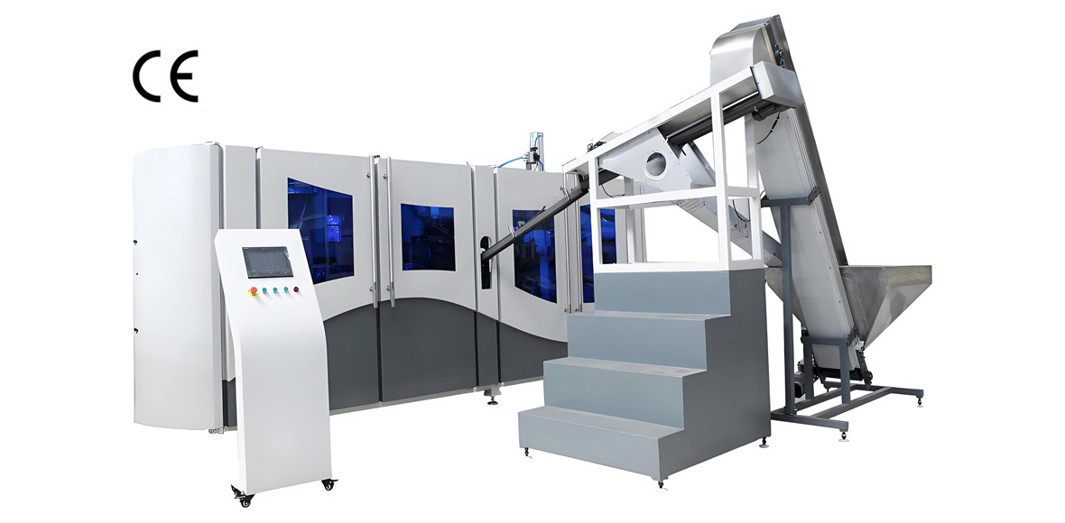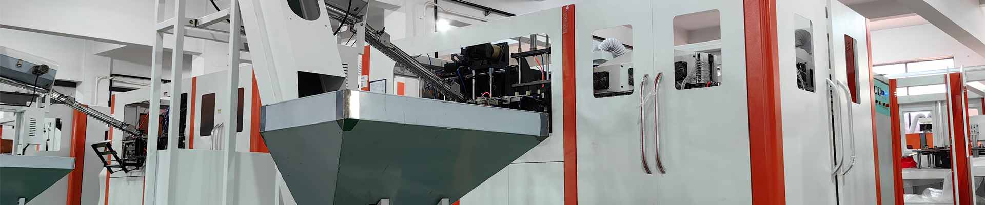
Supporting equipment configuration for a PET bottle embryo blowing production line determines far more of the final production economics than the blow molding machine itself. The blowing machine is the visible centrepiece, but the compressed air station, the chilled water system, the preform handling equipment and the electrical infrastructure together account for the majority of installed power, the majority of floor area and the majority of the problems that appear during the first six months of operation. A stretch blow molding machine rated at 12,000 bottles per hour will deliver perhaps 7,000 bottles per hour if the high-pressure compressor is undersized, if the pressure dew point drifts upward, or if the chilled water supply cannot hold the mould at a stable temperature during a summer afternoon shift.
This guide sets out the complete supporting equipment configuration for a PET bottle embryo blowing production line, working outward from the blowing machine to the utilities that feed it. It covers infrared oven lamp power and zoning, high-pressure air generation at 30 to 40 bar with adsorption drying to a -40 degrees C dew point and 0.01 micrometre filtration, air recovery systems that return 30 to 40 percent of blowing air to the low-pressure network, chiller capacity matching for the 8 to 12 degrees C mould circuit and the 15 to 20 degrees C hydraulic circuit, cooling tower sizing, preform elevators and unscramblers, air conveying, mould quick-change strategy, filling line integration, transformer and switchgear capacity, purified water and CIP, compressor room layout with noise control, and the energy consumption split across the whole line expressed as percentage shares and kWh per 1000 bottles.
The technical positions below reflect field practice at YuDa, a Wanplas factory with more than twenty years of specialisation in PET bottle blow molding machines, exports to over sixty countries, more than twenty patents, and a position among the top two Chinese manufacturers in this category. Where a parameter varies with bottle geometry, resin grade or ambient conditions, the range is given rather than a single number, along with the reasoning needed to select within that range. Every figure in this article should be treated as a starting point for engineering confirmation against the specific bottle drawing, the site altitude and the local ambient design conditions, not as a substitute for a project-specific utility calculation.
Line Architecture: What a PET Bottle Embryo Blowing Production Line Actually Contains
A PET bottle embryo blowing production line is a chain of eleven functional blocks, of which the blow molding machine is only one. Understanding the chain is the precondition for correct supporting equipment configuration, because each block imposes its own utility demand, its own footprint and its own failure mode on the others. Treating the line as “a blower plus some accessories” is the single most common cause of capacity shortfall on new installations.
The functional blocks, in process order, are: preform storage and conditioning; preform elevating and unscrambling; preform feeding rail and neck-support transfer; the infrared preheating oven; the stretch-blow station with mould clamping and stretch rod servo; the bottle discharge and air conveyor; the rinser; the filler; the capper; labeling and coding; and finally shrink wrapping or case packing with palletizing. Running in parallel and feeding all of these are the utility blocks: the high-pressure air station, the low-pressure air station, the chilled water plant, the cooling tower circuit, the purified water treatment plant, the CIP skid, and the electrical distribution room.
Two architectural decisions cascade through everything else. The first is whether the line is a two-step process, in which preforms are injection moulded separately (often on a different site) and blown later, or a single-step integrated line. Almost all high-volume beverage production uses the two-step route, because it decouples preform supply from bottle demand and allows preforms to be bought in. In the two-step architecture the blowing line does not need a preform dryer for resin, but it does need preform conditioning and, where preforms are stored in humid warehouses, a controlled acclimatisation period of eight to twenty-four hours before blowing so that preform body temperature entering the oven is stable within plus or minus 3 degrees C.
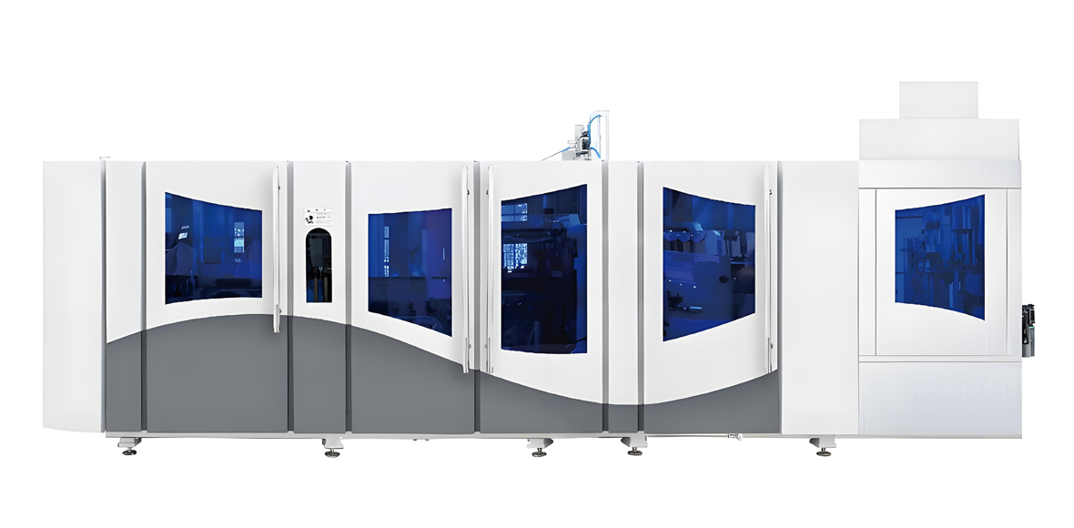
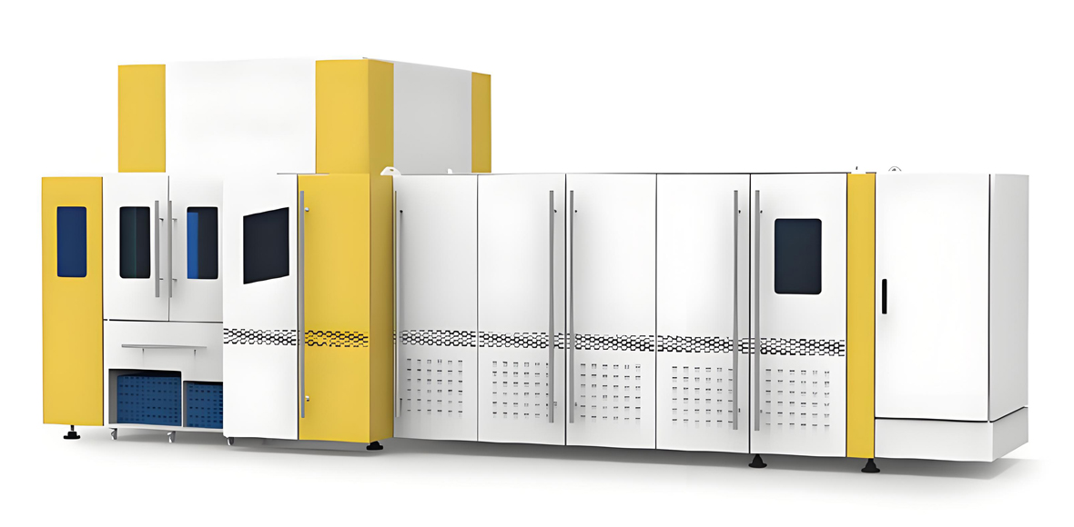
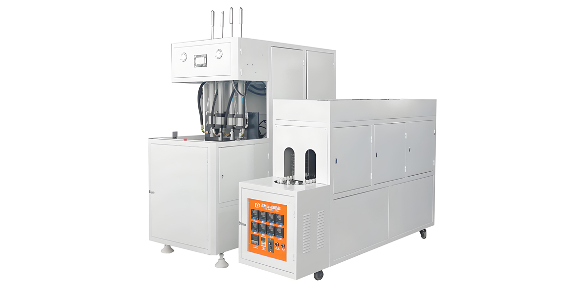
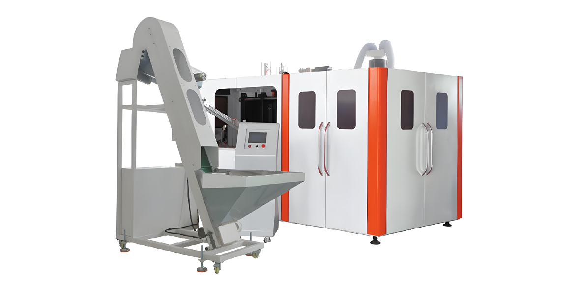
The second decision is between a linear machine and a rotary machine. Linear machines index preforms in groups through a straight oven and clamp them in a linear mould carrier; they are mechanically simpler, cheaper to tool, tolerant of frequent format changes, and typically deliver 1,100 to 1,500 bottles per hour per cavity. Rotary machines carry preforms on a continuously turning wheel with individual mould stations; they achieve 2,000 to 3,000 bottles per hour per cavity, run more stably at high speed, and are the only practical choice above roughly 15,000 BPH. YuDa’s FGX high-speed series is built around this rotary principle, with a single mould station rated at 2,500 to 3,000 BPH and total machine outputs of 8,000 to 15,000 BPH; the standard full-automatic series covers 1,000 to 7,000 BPH, and the semi-automatic series serves small enterprises where procurement cost matters more than labour cost.
Everything downstream of the blowing machine must be dimensioned on the blowing machine’s nominal rate plus a buffer margin, and everything upstream must be dimensioned on the same nominal rate plus a scrap allowance. A useful rule is that the filler should be sized 5 to 10 percent above the blower’s nominal BPH, so that the blower is never the constraint on the filler, and the preform feeding system should be sized 10 to 15 percent above, so that rail starvation never propagates a gap through the oven.
Blow Molding Machine Selection: Capacity Tiers and the Supporting Equipment Matrix
Blow molding machine capacity tiers drive every downstream utility decision, so the correct sequence is to fix the machine tier first and then read off the supporting equipment. The table below maps five practical capacity tiers to the corresponding compressor, dryer, chiller, cooling tower, conveying and electrical requirements for a 500 ml still-water bottle with a 24 to 26 gram preform, which is the reference product used throughout this article.
Capacity Tier to Supporting Equipment Selection Matrix
| Parameter | Tier 1: 800-1,500 BPH | Tier 2: 2,000-4,000 BPH | Tier 3: 5,000-8,000 BPH | Tier 4: 9,000-12,000 BPH | Tier 5: 13,000-20,000 BPH |
|---|---|---|---|---|---|
| Machine architecture | Semi-automatic, 1-2 cavity | Linear full-auto, 2-4 cavity | Linear full-auto, 4-6 cavity | Rotary high-speed, 4-6 cavity | Rotary high-speed, 6-10 cavity |
| Oven installed power | 12-24 kW | 30-55 kW | 60-100 kW | 110-150 kW | 160-240 kW |
| HP air demand at 35-40 bar | 0.4-0.7 Nm3/min | 0.9-1.7 Nm3/min | 2.1-3.4 Nm3/min | 3.8-5.2 Nm3/min | 5.5-8.6 Nm3/min |
| HP compressor shaft power | 7.5-15 kW | 18.5-37 kW | 45-75 kW | 90-132 kW | 132-200 kW |
| HP receiver volume | 0.3-0.5 m3 | 0.5-1.0 m3 | 1.0-1.5 m3 | 1.5-2.0 m3 | 2.0-3.0 m3 |
| Mould chiller (8-12 degrees C) | 5-8 kW | 10-18 kW | 22-35 kW | 38-52 kW | 55-85 kW |
| Oil / drive chiller (15-20 degrees C) | 3-5 kW | 6-10 kW | 12-18 kW | 20-28 kW | 30-45 kW |
| Cooling tower duty | 20-35 kW | 45-80 kW | 100-160 kW | 180-260 kW | 280-420 kW |
| Preform unscrambler rate | 2,000/h | 5,000/h | 10,000/h | 15,000/h | 24,000/h |
| Blowing block installed capacity | 40-60 kVA | 80-140 kVA | 160-250 kVA | 300-400 kVA | 420-630 kVA |
| Indicative total investment level | Low | Medium | High | Very High | Premium |
Three notes on reading this matrix. First, the air demand figures assume a 500 ml bottle; scaling to other volumes is close to linear in bottle volume, so a 1.5 litre bottle at the same BPH will roughly triple the air demand and force the compressor one or two frame sizes higher. Second, the oven installed power is nameplate, not average draw; a well-tuned oven with reflective side walls and correct lamp zoning typically runs at 55 to 70 percent of nameplate in steady state. Third, the electrical capacity shown covers the blowing block only. Adding a filler, labeller, packer and palletizer typically adds a further 80 to 200 kVA depending on whether the filler is gravity, isobaric or hot-fill.
Preheating Oven Design: Infrared Lamp Power, Zoning and Temperature Control
The infrared preheating oven is where bottle quality is won or lost, because the axial and radial temperature profile imposed on the preform body determines wall thickness distribution in the finished bottle. A correctly configured oven brings the preform body to a surface temperature of 100 to 115 degrees C while keeping the neck finish below 60 degrees C, and it does so with a deliberate temperature gradient rather than a uniform heat.
Ovens are built from quartz halogen infrared lamps arranged in horizontal rows, with the preform rotating on a spindle as it travels through the tunnel. Individual lamps are typically rated 1,500 W, 2,000 W, 2,500 W or 3,000 W at 220 to 240 V, with a peak emission wavelength between 1.0 and 1.4 micrometres chosen because PET absorbs strongly in this near-infrared band. The lamps are grouped into vertical zones, each zone independently power-controlled from 0 to 100 percent through a thyristor or solid-state relay module driven by the PLC recipe. Six to twelve vertical zones is standard: six for short preforms used in 330 to 600 ml bottles, ten to twelve for the long preforms used in 1.5 to 2 litre bottles where axial material distribution is more demanding.
Lamp count scales with throughput. A tier 2 linear machine may carry 24 to 40 lamps in a single oven tunnel; a tier 4 rotary machine typically carries 90 to 140 lamps distributed across two or three oven modules. YuDa’s energy-saving oven design compresses the distance between the lamp bank and the preform surface to 38.1 mm, which raises the radiative view factor and allows the same preform temperature to be reached at lower lamp power. In practice this yields electricity savings exceeding 30 percent compared with conventional heating ovens at a larger pitch, and it also shortens the oven tunnel, which reduces machine footprint and heat rejection into the workshop.
Typical Oven Zoning and Power Profile
| Zone (top to bottom) | Preform region heated | Typical power setting | Effect on bottle if set too high |
|---|---|---|---|
| Zone 1 (under neck) | Neck support ring transition | 15-35 percent | Neck ovality, thread deformation, capping leaks |
| Zone 2-3 (shoulder) | Shoulder forming region | 55-75 percent | Thin shoulder, top-load failure, pearling |
| Zone 4-7 (body) | Main panel and label area | 70-90 percent | Overheating haze, excessive shrinkage, sticking |
| Zone 8-10 (lower body) | Grip zone and base transition | 60-80 percent | Material pulled from base, thin heel |
| Zone 11-12 (gate area) | Injection gate and base centre | 25-50 percent | Gate crystallinity loss, base stress cracking |
Three auxiliary systems make the oven work reliably. The first is neck cooling: a water-cooled shield or a forced air curtain protects the neck finish, fed from the 8 to 12 degrees C chilled water circuit at 10 to 25 litres per minute depending on machine size. The second is the oven ventilation fan, which removes convected heat and prevents localised hot spots; typical fan power is 1.5 to 5.5 kW with air changes tuned so that oven ambient stays 8 to 15 degrees C above workshop ambient. The third is closed-loop temperature feedback: a pyrometer at the oven exit reads preform surface temperature and trims lamp power automatically, holding the exit temperature within plus or minus 1.5 degrees C across a shift. Without pyrometer feedback, ambient swings of 10 degrees C between night and day shift will shift bottle weight distribution enough to fail top-load testing.
A practical commissioning point: always set the oven with the machine at production speed, never at jog speed. Radiative heat input is time-dependent, so a recipe developed at reduced speed will overheat the preform when the line reaches nominal BPH, producing haze and base whitening within minutes.
High-Pressure Air System: Compressor, Receiver, Dryer, Filtration and Air Recovery
The high-pressure air station is the most important single item of supporting equipment on a PET bottle embryo blowing production line, and it is the item most often specified incorrectly. Blowing air must arrive at the valve block at 30 to 40 bar, dry to a -40 degrees C pressure dew point, filtered to 0.01 micrometre, and with stable pressure during the millisecond-scale blow pulse. Any deviation shows up immediately as bottle defects or as an inability to hold rated speed.
Compressor Selection
PET blowing uses multi-stage reciprocating (piston) compressors, typically three or four stages with intercoolers between each. Screw compressors are not used for the high-pressure duty because their practical ceiling is around 13 bar; where a screw machine is present in a PET plant it serves the low-pressure network or acts as the booster’s first stage in a combined package. Oil-free piston compressors avoid oil carry-over entirely and are preferred for food and pharmaceutical bottling; oil-lubricated machines are acceptable when followed by a properly maintained coalescing and activated carbon filtration train. Major suppliers active in this segment include Atlas Copco, Ingersoll Rand, Kaeser, Shanggu and Shenjiang, and most PET plants standardise on one brand across the station to simplify spare parts.
Compressor sizing starts from air consumption per bottle. For a rigid 500 ml bottle blown at 35 bar, the air actually enclosed in the bottle at end of blow is roughly the bottle volume multiplied by the absolute pressure ratio, which gives about 18 normal litres. Adding mould cavity dead volume, manifold volume and valve losses raises this to 18 to 26 Nm3 per 1000 bottles. Multiply by nominal BPH, add 15 to 20 percent design margin for filter pressure drop, network leakage and future format changes, and the result is the required free air delivery at the stated discharge pressure.
High-Pressure Air System Parameter Table
| Component | Specification target | Sizing rule | Consequence of undersizing |
|---|---|---|---|
| HP compressor | 30-40 bar discharge, 3-4 stage piston | 18-26 Nm3 per 1000 bottles (500 ml) plus 15-20 percent margin | Pressure sag during blow pulse, thin bottle base, speed derating |
| Pre-blow regulation | 8-12 bar, independently regulated | Separate regulator per mould station or per manifold | Off-centre bubble, uneven wall, pearlescence |
| HP air receiver | Rated at least 1.25 times working pressure | Approx. 300-400 litres per Nm3/min of delivery | Compressor short-cycling, valve wear, pressure ripple |
| After-cooler | Approach 8-12 degrees C over cooling water | Water flow 1.5-2.5 m3/h per 100 kW compressor power | Downstream dryer overload, liquid water carry-over |
| Adsorption (desiccant) dryer | Pressure dew point -40 degrees C | Twin-tower, heatless or heated purge; purge loss 4-15 percent | Ice in valve block, erratic blow timing, corrosion |
| Refrigerated dryer (LP network) | Pressure dew point +3 degrees C | Sized on LP flow at 0.8-1.0 MPa, ambient 38-45 degrees C | Condensate in solenoids, sticking cylinders |
| Filtration train | 1 micrometre pre-filter, 0.01 micrometre coalescer, carbon tower | Oil carry-over at or below 0.01 mg/m3 after coalescer | Oil film inside bottle, taint, food contact non-conformance |
| Air recovery unit | Recovers 30-40 percent of blow air at 8-12 bar | Recovered volume must not exceed LP network demand | Lost saving opportunity; oversizing wastes capital |
| HP piping | Stainless or certified pressure pipe, velocity below 15 m/s | Total pressure drop station to valve block below 1.5 bar | Compressor must run higher, energy penalty of 6-8 percent per bar |
Air Recovery: The Highest-Return Option on the Line
Air recovery is the single most cost-effective energy option available on a PET bottle embryo blowing production line. At the end of the blowing cycle, the air inside the finished bottle is still at 25 to 35 bar and is conventionally exhausted to atmosphere through a silencer. A recovery system instead routes that exhaust through a check valve arrangement into a buffer vessel, where it settles at 8 to 12 bar and is fed into the plant low-pressure network to drive cylinders, valves, rinser air knives and conveyor blow-off nozzles.
Recoverable volume is 30 to 40 percent of the blow air on typical bottle geometries, with the upper end achievable on larger bottles where the ratio of enclosed volume to dead volume is more favourable. Because the recovered air displaces low-pressure air that would otherwise have been produced by a separate screw compressor, the saving compounds: on a tier 4 line, recovery commonly eliminates the need for a dedicated 22 to 37 kW low-pressure compressor entirely and removes 6 to 12 percent from total line electricity. Two design cautions apply. First, recovered air carries the same moisture and particulate load as the blowing air, so it must be filtered before entering the low-pressure network. Second, the recovered volume must be matched to genuine low-pressure demand; if the plant cannot absorb it, the surplus vents and the investment returns nothing.
A second efficiency measure worth specifying at the design stage is pressure cascading. Not every bottle needs 40 bar. Lightweight 330 to 600 ml water bottles with simple geometry often blow acceptably at 26 to 30 bar, while complex CSD bottles with petaloid bases and hot-fill containers with heavy ribbing need 35 to 40 bar. Since compressor specific power rises roughly 6 to 8 percent for each additional bar of discharge pressure in this range, running the station at the lowest pressure that produces conforming bottles is a permanent saving that costs nothing to implement beyond disciplined recipe management.
Low-Pressure Air, Chiller Sizing and Cooling Tower Matching
The low-pressure and cooling utilities are less glamorous than the high-pressure station but they set the stability of the process. Low-pressure air at 0.8 to 1.0 MPa drives every pneumatic actuator on the line; chilled water at two distinct temperatures removes heat from moulds and hydraulics; and a cooling tower rejects the combined condenser and compressor heat to atmosphere.
Low-Pressure Air Network
Low-pressure demand on a PET line comes from mould clamping cylinders on hydraulic-pneumatic machines, preform transfer star wheels, stretch rod assist on some designs, bottle blow-off and air knives, rinser grippers, capper chucks and the labeller. Total demand runs from about 0.5 Nm3/min on a tier 1 line to 3 to 5 Nm3/min on a tier 5 line with full downstream packaging. Specify 0.8 to 1.0 MPa at the machine inlet, a refrigerated dryer to a +3 degrees C pressure dew point, 1 micrometre filtration, and a receiver of 1 to 3 m3 to smooth demand peaks from the packer and palletizer, which are highly intermittent consumers.
Note that the bottle air conveyor is not a compressed air consumer in the usual sense. Air conveyors move empty bottles by neck support using high-volume low-pressure air produced by centrifugal blowers at 0.02 to 0.05 bar, not by the compressed air network. Blower power runs 5.5 to 15 kW depending on conveyor length and bottle size, and the blower air must be filtered to at least 5 micrometre because it contacts the bottle interior region near the neck.
Chilled Water: Two Circuits, Two Temperatures
Splitting the chilled water into a cold mould circuit and a warmer mechanical circuit is standard practice and materially reduces energy consumption. The mould circuit runs at 8 to 12 degrees C and serves the blow mould bodies, the base mould inserts and the neck cooling shields; its job is to freeze the bottle shape quickly and repeatably, and colder water here directly shortens cycle time and improves dimensional stability. The mechanical circuit runs at 15 to 20 degrees C and serves hydraulic oil coolers, servo drive cabinets, the compressor after-coolers and the vacuum pump where fitted; running this circuit warmer prevents condensation on hydraulic lines and cabinet interiors and allows a chiller with a higher evaporating temperature and therefore a better coefficient of performance.
Cooling System Capacity Matching Table
| Nominal line output | Mould circuit load (8-12 degrees C) | Mould circuit flow | Oil circuit load (15-20 degrees C) | Cooling tower duty (incl. compressor) | Tower water flow |
|---|---|---|---|---|---|
| 1,500 BPH | 6-8 kW | 1.2-1.6 m3/h | 3-5 kW | 25-35 kW | 5-7 m3/h |
| 4,000 BPH | 16-20 kW | 3.0-4.0 m3/h | 8-11 kW | 70-90 kW | 13-17 m3/h |
| 6,000 BPH | 24-30 kW | 4.5-6.0 m3/h | 12-16 kW | 110-140 kW | 20-26 m3/h |
| 9,000 BPH | 36-45 kW | 6.5-8.5 m3/h | 18-24 kW | 170-215 kW | 31-39 m3/h |
| 12,000 BPH | 45-55 kW | 8.5-10.5 m3/h | 22-28 kW | 220-270 kW | 40-49 m3/h |
| 15,000 BPH | 56-70 kW | 10.5-13.5 m3/h | 28-36 kW | 280-350 kW | 51-64 m3/h |
| 20,000 BPH | 75-92 kW | 14.0-17.5 m3/h | 36-46 kW | 370-460 kW | 67-84 m3/h |
The mould circuit load can be sanity-checked from first principles. A 24 gram preform cooled from roughly 105 degrees C surface temperature to 40 degrees C at demould releases about 2.7 kJ of sensible heat using a specific heat capacity near 1.9 kJ per kg per K. At 12,000 bottles per hour that is roughly 9 kW of pure product heat; the remainder of the 45 to 55 kW figure comes from mould body heat gain from the adjacent oven, radiant load, pump work, piping gain and the design margin that lets the chiller hold setpoint on the hottest day of the year. Always size the chiller against the site’s design ambient wet bulb, not against a nominal 35 degrees C rating condition, or the line will lose speed every summer.
Cooling tower duty must cover chiller condenser rejection, which is approximately the evaporator load plus compressor input, and the heat rejected by the high-pressure air compressor inter-coolers and after-coolers, which is close to 90 percent of the compressor’s shaft power. Add 15 percent fouling margin and specify a tower approach of 4 to 5 degrees C above design wet bulb. Fit a plate heat exchanger between the tower loop and the machine loop wherever tower water quality is uncertain, and treat tower water for scaling and Legionella control in line with local regulation.
Preform Drying, Elevating, Unscrambling and Bottle Air Conveying
Preform handling equipment is inexpensive relative to the blowing machine but causes a disproportionate share of unplanned stoppages. The chain is preform hopper, inclined elevator, unscrambler, feeding rail, and neck-support transfer into the oven, followed on the discharge side by bottle takeout and air conveying to the filler.
Preform Drying: Only Relevant in the Injection Stage
Resin drying belongs to the preform injection moulding stage, not the blowing stage, but it is included here because many PET packaging projects install both. PET is hygroscopic and hydrolyses in the melt if wet, causing intrinsic viscosity loss, brittle preforms and acetaldehyde generation. The dehumidifying dryer must deliver process air at a -40 degrees C dew point and hold resin at 160 to 175 degrees C for four to six hours residence, bringing moisture below 50 ppm and preferably to 20 to 30 ppm for bottle-grade resin. Process airflow is sized at roughly 3.6 to 4.0 m3 per hour for every kg per hour of throughput, and the desiccant bed must be regenerated at 280 to 300 degrees C. Over-drying is also a fault: holding bottle-grade PET above 175 degrees C for extended periods accelerates thermal degradation and colour shift.
For the blowing stage itself, preforms need conditioning rather than drying. Preforms taken from a cold warehouse into a warm humid workshop will condense surface moisture, which flashes in the oven and creates local cold spots. Allow eight to twenty-four hours of acclimatisation in the production area, and keep preform storage between 15 and 30 degrees C with relative humidity below 65 percent. Preforms stored longer than six months should be checked for acetaldehyde and for neck ovality before a long production run.
Elevator, Unscrambler and Feeding Rail
The preform elevator is a cleated inclined belt or a bucket conveyor lifting preforms from a floor hopper to the unscrambler inlet, typically 2.5 to 4.5 metres high with 0.75 to 2.2 kW drive power and a variable frequency drive slaved to a level sensor at the unscrambler. Hopper capacity should hold at least twenty minutes of production; for a 12,000 BPH line that is 4,000 preforms or more, which usually means a hopper of 1.5 to 3 m3.
The unscrambler, sometimes called a preform orienting or sorting machine, receives bulk preforms and delivers them neck-up in single file. Rotary disc unscramblers with a centrifugal bowl handle 5,000 to 24,000 preforms per hour and are the standard choice; they should always be specified at 20 to 30 percent above line rate so that the feeding rail stays full and the blowing machine never starves. Reject chutes must return misoriented preforms to the hopper without dropping them onto the floor, and the discharge rail should include a gravity accumulation section of at least sixty seconds of buffer plus a full-rail sensor that stops the unscrambler cleanly.
Common faults here are worth listing because they repeat across installations: preform scuffing from an over-speed unscrambler disc, which shows as scratch lines on the bottle body; rail jams caused by mixed neck finishes after a format change; and static build-up in dry climates that makes preforms cling to the rail, which is cured by an ionising bar rather than by increasing rail slope.
Bottle Discharge and Air Conveying
Empty PET bottles are far too light for conventional belt conveying at speed, so they are transported by air conveyor, in which a blower-fed plenum blows filtered air across the neck support ring while the bottle hangs between guide rails. Design velocity is 25 to 60 metres per minute; conveyor width and rail spacing are set by neck ring diameter, most commonly 28 mm PCO or 30/25 finishes for water. The air conveyor is also the line’s accumulation buffer: sizing it to hold 30 to 90 seconds of production means a short stoppage at the filler does not immediately stop the blower, which matters because restarting a blowing machine costs several minutes of oven re-stabilisation and produces scrap bottles.
Specify the conveyor blower with filtration on the intake, position intakes away from forklift traffic and boiler exhausts, and include an air knife section before the rinser to remove any dust. Where the plant blows and fills in one hall, keep the air conveyor as short as practical, since every extra ten metres adds blower power and adds another place for bottles to fall over.
Molds, Cavity Strategy and Quick Changeover Systems
Mould strategy determines both the line’s output and its flexibility, and the quick changeover system determines how much of the theoretical capacity is actually available. On lines that run three or more bottle formats, changeover time frequently costs more output than machine downtime does.
Blow moulds for PET are normally machined from aluminium alloy for the body shells, because aluminium’s high thermal conductivity extracts heat quickly, with stainless steel base inserts where the petaloid geometry requires wear resistance. Cooling channels should be drilled to follow the cavity profile at a constant 10 to 15 mm from the surface, and each shell should have its own supply and return so that a single blocked channel can be diagnosed by temperature difference rather than by trial and error. Mould surface temperature is normally held between 10 and 18 degrees C for water and CSD bottles; hot-fill bottles require heat-set moulds running at 120 to 150 degrees C with an entirely different oil-based temperature control unit and are a separate engineering case.
Cavity count follows directly from the target output and the per-cavity rate. Because per-cavity rate is fixed by the physics of heating and cooling a given preform, the only route to higher output is more cavities, and more cavities means a larger oven, a bigger compressor and a heavier machine frame. This is why the supporting equipment matrix scales the way it does.
Mould Changeover Comparison
| Changeover approach | Typical time (4-6 cavity) | Tooling investment level | Best suited to |
|---|---|---|---|
| Conventional bolted shells | 90-150 minutes | Low | One or two formats, long runs |
| Quick-clamp shell system | 30-50 minutes | Medium | Three to five formats, weekly changes |
| Cassette / modular mould carrier | 15-30 minutes | High | Contract blowers, daily changes |
| Base-mould-only change (same body) | 10-20 minutes | Low | Same body, different base geometry |
| Neck finish change (spindles and grippers) | Add 40-90 minutes | Medium | Mixed water and CSD portfolios |
YuDa’s modularised machine design targets exactly this problem: mould carriers, transfer arms and oven spindles are built as replaceable modules so that a format change is a module swap rather than a rebuild, and the same modular philosophy reduces the spare parts inventory a plant must carry. The unique cam linking system that integrates mould opening, mould locking and bottom mould elevation into a single coordinated movement also reduces the number of independently adjustable mechanisms that must be re-set after a changeover, which is where most of the lost time actually goes.
Two operational habits shorten changeover more than any hardware: pre-heating replacement moulds on a trolley to near working temperature before installation, which avoids twenty minutes of thermal stabilisation, and storing every proven recipe in the PLC so that lamp zone powers, pre-blow timing, stretch rod profile and blow pressure are recalled rather than re-tuned.
Downstream Integration: Filling, Labeling, Coding, Packing and Palletizing
Downstream equipment must be matched to the blowing machine on rate, on bottle handling geometry and on control interface, and the matching must be done at the design stage rather than after both machines arrive. The three interfaces that matter are mechanical rate, neck finish compatibility and the electrical handshake that lets the blower slow down when the filler backs up.
The rinser-filler-capper monobloc is the heart of the downstream section. Filler valve count follows from bottle rate: for still water in 500 ml bottles a gravity or low-vacuum valve handles roughly 300 to 450 bottles per hour, so a 12,000 BPH line needs a filler in the 32 to 40 valve range, usually configured as a 40-32-10 or 32-24-8 rinser-filler-capper block. Carbonated soft drinks need isobaric filling, lower fill speeds and a counter-pressure system, which typically raises valve count by 25 to 40 percent for the same output. Hot-fill juice at 85 to 92 degrees C requires heat-set bottles, a different mould configuration and a bottle cooling tunnel after capping.
Labeling follows filling. OPP hot-melt roll-fed labellers handle 12,000 to 36,000 BPH and are the dominant choice for water and CSD; shrink sleeve applicators with a steam or hot-air tunnel are used where full-body decoration is needed and run 6,000 to 24,000 BPH; self-adhesive labellers suit lower speeds and premium formats. Coding is done with continuous inkjet or laser marking directly after the labeller, printing batch and expiry data; laser coders avoid consumable ink but require extraction of the fume plume.
End of line comprises a shrink wrapper running 15 to 30 packs per minute, or a wrap-around case packer for export formats, followed by a robotic or gantry palletizer handling 40 to 100 layers per hour and a stretch wrapper. Between each of these, accumulation tables of 30 to 120 seconds prevent a stoppage in one machine from propagating back to the blower. Faygo, another Wanplas factory, supplies mineral water and beverage filling lines that are designed to interface directly with YuDa blowing machines, which removes the integration risk that arises when a blower and a filler are bought from unrelated suppliers with different control philosophies.
Trim, start-up bottles and reject bottles should not be treated as waste. In-house grinding of rejected bottles and preforms into flake, followed by reprocessing, is standard practice in mature plants; Polyretec, a Wanplas factory specialising in recycling equipment, supplies PET crushing and washing lines from 500 kg/h to 6,000 kg/h, and Wanplas’s Kerke factory supplies twin-screw extruders for the subsequent pelletizing step. Even where rPET is not used in food-contact bottles, recovered material has value in strapping, fibre and non-food packaging.
Utilities Infrastructure: Power Distribution, Purified Water, CIP and Compressor Room Layout
Utilities infrastructure is the part of the supporting equipment configuration that is hardest to change later, so it deserves the most conservative design margins. Electrical capacity, water treatment and the compressor room layout are effectively permanent decisions once the building is finished.
Electrical Capacity and Distribution
Total installed capacity for a complete PET bottle line is the sum of the blowing block, the air station, the cooling plant, the filling block and the packaging block. For a 12,000 BPH water line a typical installed load lands between 550 and 750 kVA, which usually means a 630 or 800 kVA transformer with the blowing machine, the compressor and the chiller each on their own dedicated feeder. Specify separate distribution cabinets for the blowing machine, the air station, the cooling plant and the filling block, with metering on each so that the energy split can actually be measured rather than estimated.
Three electrical details repeatedly cause commissioning delays. Harmonic distortion from the oven’s thyristor power controllers and from the many variable frequency drives on the line can exceed limits at the point of common coupling; specify line reactors or active harmonic filters where the utility enforces a total harmonic distortion limit. Power factor drops when the compressor runs unloaded, so include capacitor bank correction with detuned reactors. And voltage dip ride-through matters: a 200 millisecond dip that trips the blowing machine will scrap an oven-full of preforms, so critical control circuits deserve an uninterruptible supply. Machine electrical design should follow IEC 60204-1 for safety of machinery electrical equipment, and CE marking requirements apply for European destinations.
Water Treatment and CIP
Where the line fills drinking water, the water treatment plant is part of the line, not an accessory. A conventional train is raw water tank, multimedia filter, activated carbon filter, softener, security cartridge filter at 5 micrometre, reverse osmosis, storage tank, ultraviolet sterilisation and ozone dosing at 0.2 to 0.4 ppm for the rinse and fill water. Product contact surfaces should be 304 or 316L stainless steel with sanitary welds, and the loop should maintain a velocity above 1.5 m/s to prevent biofilm.
Clean-in-place equipment is a skid with caustic and acid tanks, a heater, a supply pump and a return pump. A standard cycle is a water pre-rinse, a caustic wash at 1.5 to 2.5 percent concentration at 75 to 80 degrees C for 15 to 20 minutes, an intermediate rinse, an acid wash at 1 to 2 percent for 10 to 15 minutes, a final rinse with treated water and, where required, a hot water or steam sanitisation. CIP frequency for still water is usually every 24 to 72 hours of production. Food contact compliance for bottles and contact parts is governed by FDA regulations in the United States, EU 10/2011 in Europe and GB 4806 series standards in China; ISO 22000 or an equivalent food safety management system usually frames the whole plant’s hygiene programme.
Compressor Room Layout and Noise Control
The compressor room deserves specific design attention because it concentrates noise, heat and maintenance activity in one place. High-pressure piston compressors generate 85 to 95 dB(A) at one metre; an acoustic enclosure or a dedicated room with absorptive lining brings the workshop level down to 75 dB(A) or lower, which is normally the target for an eight-hour exposure without hearing protection. Locate the room on an external wall so that intake and discharge ventilation are short and direct, and keep it as close to the blowing machine as the layout allows, since every metre of 40 bar pipe adds pressure drop and cost.
Ventilation is the most common design error. A 132 kW compressor rejects close to 120 kW of heat, and if the room cannot exhaust it the intake air temperature rises, the compressor’s volumetric efficiency falls and the discharge temperature alarm eventually trips the machine. Design for 20 to 30 air changes per hour, keep room temperature below 40 degrees C at design ambient, and place the intake low and the exhaust high. Allow at least one metre of clearance on all sides of each compressor for valve and piston ring service, provide a lifting beam or hoist point above the cylinder heads, and specify a floor drain with an oil-water separator for condensate. Recovering compressor waste heat into pre-heated washdown water is a straightforward option in temperate climates and can capture 70 to 80 percent of the compressor’s input energy as usable low-grade heat.
Energy Consumption Breakdown and Practical Efficiency Measures
Energy is the dominant controllable operating cost on a PET bottle embryo blowing production line, and compressed air is the dominant share of that energy. Understanding the split is the precondition for spending improvement effort where it pays.
Energy Share and Efficiency Measure Table
| System | Share of blowing block electricity | Typical kWh per 1000 bottles (500 ml) | Primary efficiency measure | Achievable saving on that system | Implementation cost level |
|---|---|---|---|---|---|
| High-pressure air generation | 40-55 percent | 5.5-11.0 | Air recovery plus pressure cascading to lowest workable bar | 20-35 percent | Medium |
| Infrared preheating oven | 30-40 percent | 4.5-9.0 | Reduced lamp pitch (38.1 mm), reflectors, pyrometer trim | 25-35 percent | Medium |
| Chilled water plant | 8-12 percent | 1.2-2.6 | Split circuits, free cooling in winter, variable primary flow | 15-30 percent | Medium |
| Machine drives and hydraulics | 4-8 percent | 0.7-1.8 | Servo drive conversion, variable displacement pumps | 20-40 percent | High |
| Low-pressure air and conveying | 3-6 percent | 0.5-1.4 | Leak survey, blow-off nozzle upgrade, blower VFD control | 15-25 percent | Low |
| Cooling tower and pumps | 2-4 percent | 0.3-0.9 | Fan VFD on wet bulb reset, pump impeller trim | 20-30 percent | Low |
| Lighting, HVAC, control | 1-3 percent | 0.2-0.7 | LED retrofit, zone control | 30-50 percent | Low |
Read the table with the shares and the absolute numbers together. A 30 percent saving on lighting sounds impressive but moves total consumption by well under 1 percent, whereas a 25 percent saving on the air station moves the total by 10 to 14 percent. The correct priority order for an existing plant is therefore: fix compressed air leaks first because the measure costs almost nothing; drop blowing pressure to the minimum that produces conforming bottles; install or commission air recovery; then address the oven with reflectors, correct lamp pitch and pyrometer trim; then optimise the chilled water setpoints and enable winter free cooling; and only then consider drive-level retrofits.
Compressed air leakage deserves emphasis. On a network that has run for several years without a leak survey, 15 to 25 percent of generated low-pressure air commonly escapes through fittings, quick couplers, hose splits and stuck drain valves. On the high-pressure side leakage is less voluminous but far more expensive per unit volume because of the compression energy embodied in it. An ultrasonic leak survey conducted twice a year, with tagged repairs closed out during planned maintenance, is the highest-return energy activity available to any bottling plant. Plants operating an ISO 50001 energy management system typically formalise this as a recurring action with sub-metered verification.
Finally, remember that lightweighting is an energy measure as well as a material measure. Reducing a 500 ml water preform from 24 grams to 19 grams reduces oven energy roughly in proportion to mass, reduces cooling load in the same proportion, and reduces resin consumption by over 20 percent. It also narrows the process window, so it must be validated with top-load, burst and drop testing before it goes to production.
Capacity Calculation Method and the Selection Worksheet
Capacity calculation for a PET bottle embryo blowing production line follows a simple formula, and most specification errors come from applying it in the wrong direction. The formula is: actual saleable output equals per-cavity output rate multiplied by cavity count multiplied by OEE.
Per-cavity output rate is a machine and product property. Semi-automatic machines deliver 700 to 900 bottles per hour per cavity. Linear full-automatic machines deliver 1,100 to 1,500. High-speed rotary machines such as the YuDa FGX series deliver 2,500 to 3,000 per cavity for standard water bottles, dropping to 1,600 to 2,000 for large 1.5 to 2 litre formats and to 1,200 to 1,600 for heat-set hot-fill containers where the mould dwell time is longer.
OEE is the product of availability, performance and quality. A mature line running a single format with trained operators reaches 80 to 88 percent. A line running four or five formats with frequent changeovers realistically sits at 68 to 78 percent. A new installation in its first quarter typically runs 60 to 72 percent while operators learn the recipes. Using 85 percent for a multi-format new plant is the most common planning error in this industry and produces a line that cannot meet its contracted volume.
Worked Example: Sizing for 10,000 Saleable Bottles per Hour
- Define the requirement. Target 10,000 saleable 500 ml water bottles per hour, single format, two shifts, mature operating team expected within six months.
- Select OEE. Single format, experienced team, plan at 82 percent, with a first-year interim assumption of 72 percent.
- Compute nominal requirement. 10,000 divided by 0.82 gives 12,195 BPH nominal. Round up to a 12,000 to 13,000 BPH machine class and confirm the first-year output at 72 percent, which yields about 8,900 BPH.
- Set cavity count. At 2,500 BPH per cavity on a high-speed rotary, five cavities gives 12,500 BPH nominal. Six cavities at a slightly reduced 2,200 BPH each gives 13,200 BPH with more speed margin and lower mechanical stress.
- Size the air station on nominal, not on saleable. 13,200 BPH multiplied by 22 Nm3 per 1000 bottles gives 290 Nm3/h, which is 4.8 Nm3/min; add 18 percent margin to reach 5.7 Nm3/min at 40 bar, implying a 110 to 132 kW multi-stage compressor.
- Size cooling on nominal. Interpolating the cooling table at 13,200 BPH gives roughly 50 to 60 kW on the mould circuit and 25 to 32 kW on the oil circuit, with a cooling tower duty near 250 to 300 kW once compressor rejection is added.
- Size preform feeding at 15 percent above nominal. 13,200 multiplied by 1.15 gives about 15,200 preforms per hour, so specify a 15,000 to 18,000 per hour unscrambler.
- Size the filler at 5 to 10 percent above nominal. A 14,000 BPH capable monobloc keeps the filler out of the critical path.
- Confirm electrical capacity. Blowing block near 350 to 400 kVA, air station near 160 kVA, cooling near 90 kVA, filling and packaging near 150 kVA, giving roughly 750 to 800 kVA installed and an 800 kVA transformer with future headroom.
- Verify specific energy. Target 15 to 22 kWh per 1000 bottles for the blowing block; measure it during acceptance testing with dedicated sub-meters rather than accepting a calculated figure.
The critical discipline in this worksheet is step 5. Supporting equipment must be sized on nominal machine capacity, because the compressor and chiller must serve the machine when it is running at full speed; OEE losses occur as stoppages, during which utility demand simply pauses. Sizing utilities on OEE-adjusted output guarantees that the line cannot reach its rated speed, which then depresses OEE further in a self-reinforcing loop.
Commissioning, Acceptance Testing and Common Configuration Mistakes
Commissioning is where configuration decisions are validated, and a structured acceptance test protects the buyer far more effectively than a long contractual specification. The acceptance test should be run at nominal speed, with the customer’s own preforms and the customer’s own utilities, for a continuous period long enough to expose thermal drift.
A workable acceptance protocol has six elements. Run the line continuously for at least eight hours at nominal BPH and record output every fifteen minutes. Sample bottles every thirty minutes and measure weight, wall thickness at five defined points, top-load resistance, burst pressure, base clearance and perpendicularity. Log high-pressure network pressure at the valve block with a fast data logger to confirm that the pressure sag during the blow pulse stays within 1.5 bar. Log chilled water supply and return temperature on both circuits to confirm the chiller holds setpoint. Sub-meter the blowing machine, the compressor and the chiller separately to establish the real kWh per 1000 bottles baseline. Finally, perform two full format changeovers with the plant’s own operators and time them, because a changeover time that only the supplier’s engineer can achieve is not a usable number.
The configuration mistakes that recur across projects are worth stating plainly, because each is cheap to avoid at the design stage and expensive to correct afterwards. Undersizing the high-pressure compressor by sizing it on average rather than peak demand is the most frequent. Specifying a refrigerated dryer instead of an adsorption dryer for the high-pressure circuit, which saves a modest amount initially but causes ice formation and erratic blow timing, is the second. Combining the mould and hydraulic cooling into a single 8 degrees C circuit, which wastes chiller energy and causes condensation on hydraulic components, is the third. Placing the compressor room far from the blowing machine, which adds permanent pressure drop, is the fourth. Sizing the unscrambler at exactly line rate, so that any minor jam starves the oven, is the fifth. Omitting sub-metering, which makes every subsequent energy discussion an argument about estimates, is the sixth.
Remote diagnostics change the economics of after-sales support significantly. YuDa machines include a remote monitoring system that allows engineers at the China headquarters to read PLC data over a mobile connection, review alarm history and push parameter recommendations to the customer site, so that many faults are diagnosed before an engineer travels. Combined with the Wanplas brand’s shared service commitments, which include an annual free spare parts allowance, free replacement of parts that fail within warranty, engineer-supported on-site installation and an open factory policy for pre-purchase inspection, this reduces the practical risk of buying a complete line from a single source rather than assembling it from unrelated suppliers.
It is also worth planning the spare parts inventory as part of the configuration exercise rather than after the first breakdown. The minimum stock for a PET blowing line is a full set of infrared lamps for at least one oven module, a complete set of blow valve seals and seats, stretch rod seals, one spare servo drive of each type used, one spare compressor valve set, chiller sensors, and the wear parts of the unscrambler discharge rail. Lamps in particular fail gradually rather than suddenly, and a slowly dimming lamp shifts bottle wall distribution long before it fails outright, so lamps should be replaced by scheduled group replacement rather than individually on failure.
Frequently Asked Questions
How much high-pressure air does a PET bottle embryo blowing production line consume?
For a 500 ml still-water bottle blown at 30 to 35 bar, free air demand is typically 18 to 26 Nm3 per 1000 bottles once mould cavity and manifold dead volume are included. A 12,000 BPH line therefore needs roughly 4.5 to 6 Nm3/min of continuous delivery at 40 bar, plus 15 to 20 percent design margin for filter loading, network leakage and future format changes. Larger bottles scale close to linearly with volume, so a 1.5 litre format at the same rate will roughly triple this demand and usually forces a larger compressor frame.
Why does PET blowing air need a -40 degrees C dew point and 0.01 micrometre filtration?
Air expanding rapidly from 40 bar to atmospheric pressure in the blow valve block cools sharply, and any residual moisture freezes on valve seats, causing erratic blow timing and eventually valve failure. A -40 degrees C pressure dew point from a twin-tower adsorption dryer keeps the air dry enough that this cannot occur. The 0.01 micrometre coalescing filtration with an oil carry-over limit of 0.01 mg/m3 protects the product itself, since the air contacts the inside of a food-contact container, and it supports compliance with FDA, EU 10/2011 and GB 4806 food-contact requirements alongside the ISO 8573-1 compressed air purity framework.
Should the mould cooling and hydraulic oil cooling share one chiller?
No. Blow moulds need 8 to 12 degrees C water to freeze bottle geometry quickly, but hydraulic oil coolers, servo cabinets and compressor after-coolers work perfectly well at 15 to 20 degrees C. Running the mechanical loads on the cold circuit forces the chiller to a lower evaporating temperature than necessary, which reduces its coefficient of performance, and it causes condensation on hydraulic lines and inside electrical enclosures. Two separate circuits typically cut chilled water electricity by 15 to 30 percent compared with a single cold circuit serving everything.
How much does an air recovery system actually save?
An air recovery system captures blow mould exhaust and returns 30 to 40 percent of the blowing air to the low-pressure network at 8 to 12 bar. Because that recovered air displaces low-pressure air that would otherwise be generated separately, the measure commonly removes 6 to 12 percent of total blowing block electricity and, on medium and large lines, can eliminate the need for a dedicated low-pressure screw compressor. The recovered volume must be matched to real low-pressure demand, because surplus recovered air simply vents and returns nothing.
What is the realistic energy consumption per 1000 bottles?
A well-configured blowing block producing 500 ml water bottles typically consumes 15 to 25 kWh per 1000 bottles, of which the high-pressure air station accounts for 5.5 to 11.0 kWh and the infrared oven for 4.5 to 9.0 kWh. Older lines without air recovery, with wide lamp pitch ovens and with a single cold chilled water circuit commonly exceed 30 kWh per 1000 bottles. The figure should always be measured with dedicated sub-meters during acceptance testing rather than accepted as a calculated value.
How do I calculate the real output of a blowing line?
Multiply the per-cavity output rate in bottles per hour by the number of cavities, then multiply by OEE. A six-cavity high-speed rotary machine running 2,500 bottles per hour per cavity gives 15,000 BPH nominal; at 82 percent OEE the saleable output is about 12,300 BPH. Supporting equipment must be sized on the nominal 15,000 BPH figure, because utilities have to serve the machine whenever it runs at full speed, and OEE losses appear as stoppages during which utility demand simply pauses.
What preform drying parameters apply if I also injection mould my own preforms?
Bottle-grade PET must be dried to below 50 ppm moisture, and preferably to 20 to 30 ppm, before injection. This requires a dehumidifying dryer delivering process air at a -40 degrees C dew point, resin held at 160 to 175 degrees C for four to six hours of residence, and process airflow of roughly 3.6 to 4.0 m3 per hour for each kg per hour of throughput. Insufficient drying causes hydrolytic intrinsic viscosity loss, brittle preforms and elevated acetaldehyde; excessive time above 175 degrees C causes thermal degradation and yellowing.
How long should a mould changeover take, and what determines it?
Conventional bolted shells on a four to six cavity machine take 90 to 150 minutes, quick-clamp systems take 30 to 50 minutes, and cassette-style modular carriers take 15 to 30 minutes. A neck finish change adds 40 to 90 minutes because spindles, grippers and transfer stars must all change. The two practices that shorten changeover most are pre-heating replacement moulds on a trolley before installation and storing every proven recipe in the PLC so that lamp zone powers, pre-blow timing and stretch profile are recalled rather than re-tuned.
What electrical capacity should I plan for a complete PET bottle line?
A 12,000 BPH water line typically requires 550 to 750 kVA of installed capacity across the blowing block, air station, cooling plant, filling block and packaging block, which normally means a 630 or 800 kVA transformer with dedicated feeders for the blowing machine, the compressor and the chiller. Plan for harmonic mitigation because oven thyristor controllers and variable frequency drives generate significant distortion, include power factor correction with detuned reactors, and protect critical control circuits against short voltage dips that would otherwise scrap an oven-full of preforms.
How should the compressor room be laid out?
Place the compressor room on an external wall as close to the blowing machine as the layout permits, since every metre of 40 bar pipework adds permanent pressure drop. Design ventilation for 20 to 30 air changes per hour with a low intake and a high exhaust, keeping room temperature below 40 degrees C at design ambient, because a 132 kW compressor rejects close to 120 kW of heat. Provide at least one metre of service clearance around each machine, a lifting point above the cylinder heads, a floor drain with an oil-water separator, and acoustic treatment that brings the 85 to 95 dB(A) source level down to 75 dB(A) or lower in the adjacent workshop.
Can supporting equipment be added later to expand capacity?
Some elements expand easily and others do not. Adding a second compressor in parallel, extending the air conveyor, adding accumulation tables and upgrading the unscrambler are all straightforward. Increasing transformer capacity, enlarging the compressor room, adding a second cooling tower cell or re-routing 40 bar pipework through a finished building are all disruptive and expensive. The practical rule is to size the building services, the electrical room and the compressor room for the ultimate planned capacity from day one, while installing only the machines needed for the initial phase.
Conclusion
Correct supporting equipment configuration for a PET bottle embryo blowing production line is a systems exercise, not a shopping list. The blowing machine sets the nominal rate, and every other item, from the multi-stage high-pressure compressor at 30 to 40 bar with -40 degrees C adsorption drying and 0.01 micrometre filtration, through the split 8 to 12 degrees C mould circuit and 15 to 20 degrees C mechanical circuit, to the unscrambler sized 20 to 30 percent above line rate and the transformer sized for the ultimate rather than the initial phase, must be dimensioned against that nominal rate with disciplined margins.
Three principles carry most of the value. Size utilities on nominal machine capacity rather than on OEE-adjusted output, because a starved utility depresses OEE further. Attack energy where the share is largest, which means the compressed air station at 40 to 55 percent of blowing block electricity and the infrared oven at 30 to 40 percent, using air recovery, pressure cascading, reduced lamp pitch and pyrometer trim before considering lower-impact measures. And validate the configuration with a structured acceptance test that measures real kWh per 1000 bottles with dedicated sub-meters, real changeover time with the plant’s own operators, and real bottle quality over a continuous eight-hour run rather than a short demonstration.
YuDa, a Wanplas factory with more than twenty years of dedicated experience in PET bottle blow molding machines, over twenty patents, exports to more than sixty countries and a position among the top two Chinese manufacturers in this category, supplies the FGX high-speed rotary series from 8,000 to 15,000 BPH, full-automatic machines from 1,000 to 7,000 BPH, semi-automatic machines for smaller operations, and linear blowing-filling-capping CombiBlock systems where floor area is limited. Because the wider Wanplas brand also covers filling lines through its Faygo factory, recycling equipment through Polyretec and compounding extruders through Kerke, a complete PET packaging project can be engineered, supplied and commissioned as one coordinated scope rather than as a set of independent purchases that must be reconciled on site. Buyers planning a new line in 2026 are encouraged to send the bottle drawing, the target output, the format portfolio and the site ambient design conditions so that a project-specific utility calculation and selection matrix can be prepared before any equipment is quoted.