YuDa is a Wanplas factory and one of the leading specialized manufacturers of PET bottle blow molding machines in China, with 20+ years of experience, equipment running in 60+ countries, recognition as a top 2 manufacturer of PET blow machines in China, and 20+ patents in blow molding and line integration technology. This article answers the single most common question a buyer asks after choosing a blow molding machine: what else must be purchased, installed, and verified before the line actually produces sellable bottles? The answer is a complete auxiliary equipment list, and the value of this article is that it is organized as a verifiable checklist with the selection parameters for every item rather than a vague shopping list.
Buying the stretch blow molding machine is only the first step. A complete PET bottle blowing production line is a system of systems: it needs preforms delivered and conditioned, high-pressure air to stretch and blow the PET, cooling water to hold the mold and machine at the right temperature, infrared heat to soften the preform, molds to shape the bottle, conveying to move bottles downstream, inspection to reject defects, electrical and automation to coordinate everything, and plant utilities to supply air, water, power, and drainage. Miss any one of these and the line either will not start or will produce off-spec bottles. The purpose of this guide is to make sure nothing is missed and that every selection is justified by a parameter rather than a guess.
The structure follows the physical flow of the line and then the supporting utility branches. We begin with the full logistics map, walk through nine equipment modules in the order material and energy actually move, present the real YuDa machine series with specification tables, give the consolidated auxiliary checklist split into Essential, Recommended, and Optional tiers, show three full configuration examples at small, medium, and large scale, provide a requirement-to-model selection table, list the most expensive mistakes buyers make, and finish with a commissioning and site-acceptance checklist plus a practical FAQ. By the end, a procurement or engineering team can hand a complete, parameter-backed bill of materials to its plant and to its utility contractor.
The Complete PET Bottle Blowing Line at a Glance
A complete PET bottle blowing production line is best understood as one main material flow plus four utility branches. The main flow moves the preform from storage to finished bottle and then downstream to filling or packaging. The utility branches supply the energy and control that the main flow cannot live without: compressed air, cooling water, electrical power, and vacuum or drainage where needed. Treating the line as a flow with branches, rather than as a list of machines, is the fastest way to spot what is missing.
The main material flow reads as follows. Preforms are stored in a hopper, lifted and oriented by an automatic feeder, sorted and aligned, and then conveyed into the heating oven. Inside the oven the preform is conditioned by infrared lamps to a precise temperature profile. The conditioned preform moves to the blow station, where it is stretched by a stretch rod and blown by high-pressure air inside a blow mold to form the bottle. The finished bottle is discharged, conveyed by air or belt to a buffer, and then handed to a filling or packaging operation. Waste preforms, defective bottles, and trimmings are collected for recycling.
The four utility branches run alongside this flow. The compressed air branch delivers low-pressure air for pneumatic actions and high-pressure air for the actual blow. The cooling water branch delivers chilled water to the mold and a separate tempered water loop to the machine frame and oven. The electrical branch delivers stabilized three-phase power to the servo drives, ovens, and control cabinets. The vacuum and drainage branch supports certain feeding, labeling, and cleaning steps and carries away condensate. Each branch has its own capacity requirement that must be sized from the target bottles per hour, the bottle volume, and the bottle shape, not from a rule of thumb.
Reading the line this way also reveals the dependency order. The blow machine sets the节拍, but the air system sets the ceiling on how many bottles can be blown per hour because each bottle consumes a fixed volume of high-pressure air. The cooling system sets the floor on cycle time because the mold must shed heat before the next cycle. The feeding system sets the minimum because the oven can only process as many preforms as are presented to it. When one branch is undersized, the whole line slows to that branch, and the bottleneck is rarely the blow machine itself.
Module 1: Preform Handling and Feeding
Preform handling is the first physical module after storage and the part of the line most often underestimated. A blow machine rated for 12000 BPH is useless if preforms arrive at the oven at 8000 BPH. The job of this module is to deliver the right number of correctly oriented, clean, dry, and temperature-stable preforms to the oven entrance without jamming, without contamination, and without damaging the neck finish that later seals the bottle.
The preform hopper is the buffer between bulk storage and the line. It holds a working quantity of preforms so that a minor interruption in upstream supply does not stall the oven. The hopper size should cover at least 10 to 15 minutes of line consumption, calculated from bottles per hour and the preform mass, so the operator has time to refill from the gaylord or silo without stopping the machine. A hopper that is too small causes micro-stops; a hopper that is too large wastes floor space and can over-compress light preforms.
The automatic preform elevator or feeder lifts preforms from the hopper and presents them to the sorter. Its rated capacity must exceed the oven demand, expressed in pieces per minute, by a margin of roughly 10 to 15 percent so the oven never starves. The sorter orients preforms mouth-up or mouth-down depending on the oven design and spaces them on the transfer pitch. A good sorter maintains orientation through the transfer and into the oven chain without rotation or drop shock that could scuff the preform surface.
Between the sorter and the oven, a metal detector and a dust or static removal station protect both product and machine. Metal fragments from handling or prior processing can destroy a blow mold on contact, and dust or fiber on the preform transfers to the bottle and shows as visible contamination at filling. In food and beverage plants these stations are not optional, because the preform is the food-contact surface and any foreign object is a recall risk.
Temperature conditioning of the preform is a subtle but important step, especially in cold seasons or in plants without climate control. PET preforms stored at low ambient temperature or with moisture on the surface blow inconsistently because the starting temperature and the intrinsic viscosity distribution are off. A preform drying or tempering stage, and in some climates a controlled warm-up, keeps the entering preform within a narrow window so the oven only has to do the final conditioning. This stabilizes wall thickness and reduces scrap, which matters more at high speed than at low speed.
The selection criteria for this module are summarized below. Capacity margin, orientation reliability, and contamination control are the three parameters that decide whether the module is fit for the line.
| Item | Selection parameter | How to size it | Why it matters |
|---|---|---|---|
| Preform hopper | Buffer volume in minutes of consumption | 10–15 min of BPH × preform mass | Prevents oven starvation from supply gaps |
| Elevator / feeder | Throughput in pcs/min | Oven demand × 1.10–1.15 margin | Must exceed blow demand or line slows |
| Sorter | Orientation accuracy, pitch match | Matched to oven chain pitch | Wrong orientation jams or damages neck |
| Metal detector | Aperture, sensitivity | Based on preform diameter | Protects blow mold from catastrophic damage |
| Dust / static removal | Airknife flow, ionizer | Cover transfer width | Keeps food-contact surface clean |
| Preform tempering | Target entry temperature | Set by ambient and IV grade | Stabilizes wall thickness in cold climate |
Module 2: High-Pressure Air System (The Most Critical Auxiliary)
If one auxiliary decides whether a PET blow line runs at all, it is the high-pressure air system. Stretch blow molding uses compressed air at 3.5 to 4.0 MPa to stretch and inflate the preform against the mold wall, and carbonated beverage bottles at the upper pressure end can require the full 4.0 MPa to hold their pressure resistance and base design. Low-pressure air at 0.6 to 0.8 MPa handles the pneumatic actions such as mold movement, transfer, and valve actuation, but it is the high-pressure loop that forms the bottle and therefore sets the production ceiling.
The high-pressure loop begins with a piston-type high-pressure compressor. For PET blowing, oil-free or tightly filtered piston compressors are preferred because any oil aerosol in the blowing air contacts the food-contact inner bottle surface. The compressor must deliver the sum of per-bottle air consumption across the target bottles per hour, plus a margin for valve leakage and recovery dynamics. Per-bottle consumption rises with bottle volume and with whether the bottle is a still-water type or a carbonated type, because carbonated bottles need a higher blow pressure and a firmer stretch.
Between the compressor and the machine sits a receiver tank whose volume is easy to underestimate and expensive to get wrong. The receiver smooths the pulsed demand of each blow stroke so the compressor does not see a sawtooth load, and its volume should be sized from the single-bottle air volume multiplied by the bottles per hour and by a buffering factor that covers the compressor reaction time. A receiver that is too small lets line pressure dip during the busiest part of each stroke, and that pressure dip is the classic cause of thin or uneven bottle walls that no mold change can fix.
Air quality equipment is not optional on a food line. After compression the air passes through inter-stage and after-coolers that drop the temperature and condense moisture, then through a precision filtration train that holds oil content at or below 0.01 mg per cubic meter, then through a dryer sized to the required pressure dew point. Moisture in the blowing air condenses on the cold mold and on the preform, causing fogging, hazing, and in worst cases water droplets inside the bottle. The filtration grade is a food-safety parameter, not a nice-to-have, because the air directly contacts the inside of the bottle.
A high-pressure air recovery module is strongly recommended on any line above the entry tier. During the blow stroke, a large fraction of the air in the bottle is still at usable pressure when the mold opens. A recovery module captures that air, stores it, and feeds it back into the next stroke, returning anywhere from 20 to 35 percent of the high-pressure volume depending on bottle shape and pressure. This is expressed as a recovery percentage of the air demand, not as a currency saving, and it is one of the most effective ways to reduce the compressor size and the energy load on the line.
The table below converts target bottles per hour into the high-pressure air demand, a representative receiver volume, and a guideline pipe diameter. The per-bottle figure is a representative engineering estimate for a typical 0.5 to 1.5 liter still or carbonated PET bottle and should be confirmed against the exact bottle and neck finish during final design.
| Target line (BPH) | High-pressure demand (Nm³/min, representative) | Receiver volume (m³, representative) | Supply pipe (mm, representative) | Low-pressure loop (MPa) |
|---|---|---|---|---|
| ~2000 | 0.12 – 0.20 | 1.0 – 2.0 | DN25 | 0.6 – 0.8 |
| ~6000 | 0.40 – 0.55 | 2.0 – 3.0 | DN40 | 0.6 – 0.8 |
| ~12000 | 0.80 – 1.10 | 3.0 – 5.0 | DN50 | 0.6 – 0.8 |
| ≥15000 | 1.10 – 1.50 | 5.0 – 8.0 | DN65 | 0.6 – 0.8 |
Practical notes that protect the investment: install the receiver as close to the blow machine as the layout allows to minimize pressure loss in the last meters; size the main header for the future maximum line, not only the first machine, because most plants add a second blow module later; and use a servo-controlled blow valve so that each stroke uses only the air the bottle needs rather than a fixed dump. Pressure sensors at the receiver and at the machine inlet should feed the control system so that any dip is logged and alarmed before it reaches the bottle.
Module 3: Cooling Water and Temperature Control
Cooling water is the second utility branch and the one that sets the floor on cycle time. The blow mold must remove the heat of the PET and of the compressed air expansion fast enough that the bottle can be ejected rigid, and the machine frame and oven must stay within their own temperature windows so the servo and lamp life are protected. A chiller sized too small is the most common cause of a line that runs well for an hour and then slowly loses speed as molds heat up.
The mold cooling loop is the most demanding. Chilled water at roughly 7 to 12 degrees Celsius is circulated through the mold cooling channels, and the required flow scales with the number of cavities and with the bottle surface area. A practical planning figure is tens of liters per minute per cavity, adjusted upward for larger bottles and for carbonated bottles that carry more heat. The chiller capacity must cover the steady thermal load of continuous blowing, not the load measured during a short trial, because the load only grows as the line runs.
A second, separate loop at roughly 15 to 20 degrees Celsius serves the machine structure, the oven, and the hydraulic or servo cabinets. Mixing the two loops is a mistake: the mold needs cold stable water, while the frame needs only moderate tempering, and combining them forces the chiller to over-cool the whole plant. Two independent loops with their own pumps and controls are the correct design, and the mold loop should carry the higher specification because bottle quality depends on it.
Water quality is a maintenance parameter that many buyers ignore until scale appears. Hard water deposits scale inside mold channels and on heat exchangers, choking flow and raising mold temperature until wall thickness drifts. A filtration and, where the local supply is hard, a softening or reverse-osmosis pretreatment protects the channels. A plate heat exchanger isolates the clean loop from the open cooling tower if a tower is used, so the mold never sees raw tower water that carries biological and mineral load.
Winter protection and pump specification close the module. Pumps must deliver both the flow and the head the loop needs; a pump with the right flow but insufficient head will not push water through long mold channels. In cold climates the outdoor portion of the loop needs freeze protection, either by draining or by a glycol mix, because a frozen header can crack a chiller and stop the whole plant. The planning figures below are representative starting points to be confirmed against the selected machine and local water.
| Loop | Temperature (representative) | Flow basis | Key equipment |
|---|---|---|---|
| Mold cooling | 7 – 12 °C | tens of L/min per cavity | Chiller, pump, filtered loop |
| Machine / oven | 15 – 20 °C | fixed by cabinet load | Secondary chiller or tower |
| Open cooling | ambient dependent | by tower rating | Cooling tower, plate exchanger |
| Water prep | n/a | by supply hardness | Filter, softener or RO |
Module 4: Infrared Heating and Preform Conditioning
The heating oven is where a rigid preform becomes blowable, and although it is part of the blow machine, its configuration and consumables behave like auxiliary equipment that must be specified and stocked. The oven uses infrared lamps arranged in zones, each zone independently powered, to raise the preform body to roughly 95 to 115 degrees Celsius while keeping the neck finish below about 70 degrees Celsius through active neck cooling. The body must be hot and stretchable; the neck must stay cool so the thread is not distorted and the seal is preserved.
Lamp count and zoning follow the preform length and the bottle shape. Longer preforms and bottles with a tall body need more zones and a longer oven; wide-mouth or short bottles need fewer. The lamp power per zone is set during commissioning and stored as a recipe, so the oven is really a programmable thermal conditioner. The 38.1 mm heater pitch used on YuDa ovens concentrates infrared energy with minimal loss to surrounding air and is the reason these ovens save more than 30 percent of electricity compared with conventional heating ovens that use wider spacing.
Lamp life is a consumable parameter measured in operating hours, and plants should stock spare lamps and rotate them on a schedule rather than waiting for one to fail mid-run. Reflector plates behind the lamps must be kept clean, because dust or oil film scatters infrared energy and forces the controller to push more power for the same preform temperature, raising energy and shortening lamp life. The oven also needs forced air cooling of the lamp area so the lamps and the electronics stay within rated temperature.
Preform rotation speed inside the oven is a process parameter that couples directly to wall uniformity. The preform must rotate so the infrared energy reaches all sides evenly; if rotation is uneven, one side is hotter, stretches more, and produces a thin spot that fails top-load or burst testing. The energy figure to track is kilowatt-hours per 1000 bottles, which rolls lamp power, oven length, and idle losses into one comparable number across line speeds. Lowering this number through tighter heater pitch and better zoning is a direct operating-cost gain.
Conditioning also includes the transition from oven exit to blow. The preform should arrive at the blow station within a tight temperature window and without drag-out cooling from the neck-air system. Any drift here shows up as inconsistent stretch and off-center bottles. For this reason the oven is commissioned together with the blow station as one thermal system, and its parameters are part of the machine recipe rather than a separate setting to be tuned later.
Module 5: Blow Molds and Quick-Change Tooling
The blow mold is the tool that defines the bottle, and it is the auxiliary item with the longest lead time and the highest impact on changeover cost. A PET blow mold is typically built from an aluminum alloy body for fast heat transfer, with a stainless steel base or bottom insert for wear resistance at the petaloid base of carbonated bottles. Aluminum conducts heat quickly so the mold can be cooled effectively; stainless at the base resists the abrasion of the bottle bottom landing on the mold.
Mold cooling channels are designed into the block, not added afterward. They must align with the machine’s mold cooling manifold and deliver the planned flow without air pockets, because an air pocket in a channel is a hot spot that produces a local thin wall. The internal surface is mirror-polished so the bottle releases cleanly and the finished bottle has the required surface quality; a poorly polished mold drags PET and leaves marks that are visible on a clear bottle.
Quick-change structure is a productivity feature, not a luxury, on any line that runs more than one bottle shape. The mold should mount on a standardized base with fast couplings for cooling water and, where used, for pneumatic actions, so a changeover is a slide-out and slide-in rather than a rebuild. The number of molds a plant keeps in stock and the time to switch between them decide how fast the line can respond to a change in order mix, and that responsiveness is part of the line’s effective capacity.
Mold maintenance is scheduled around cavity wear and polish degradation. After a defined number of cycles the cavity surface is reconditioned, the cooling channels are decaled, and the base insert is inspected for scoring. Treating the mold as a maintained asset rather than a disposable tool extends its life and keeps bottle quality stable across millions of cycles. For carbonated bottles the petaloid base structure must be inspected for cracking or deformation because base failure is the most common leak path on a carbonated bottle.
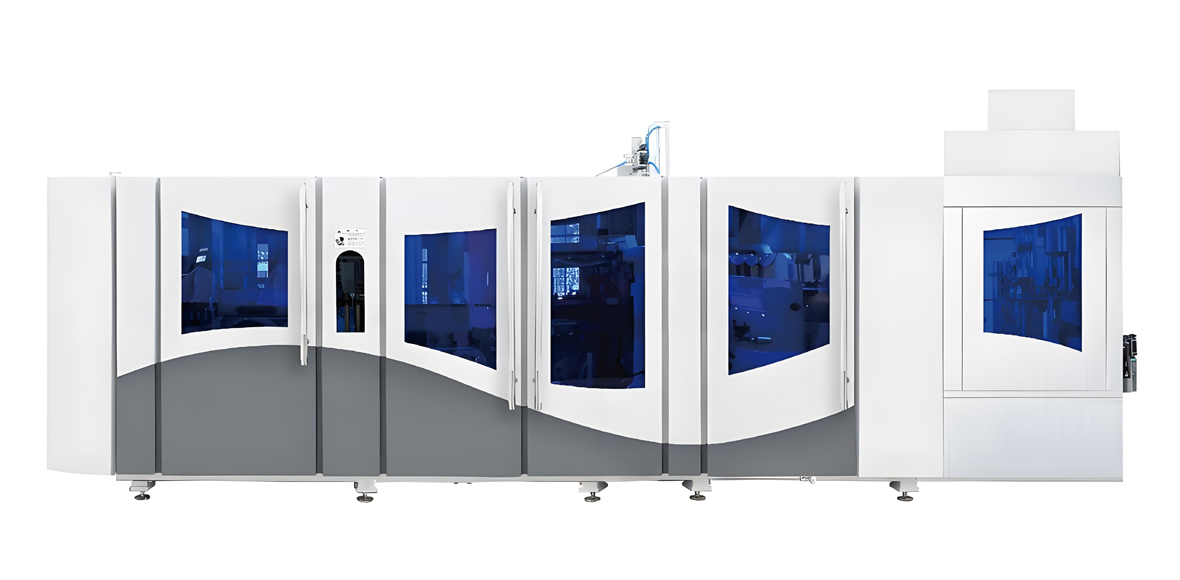
YuDa FGX High-Speed Series: Engine of the High-Volume Line
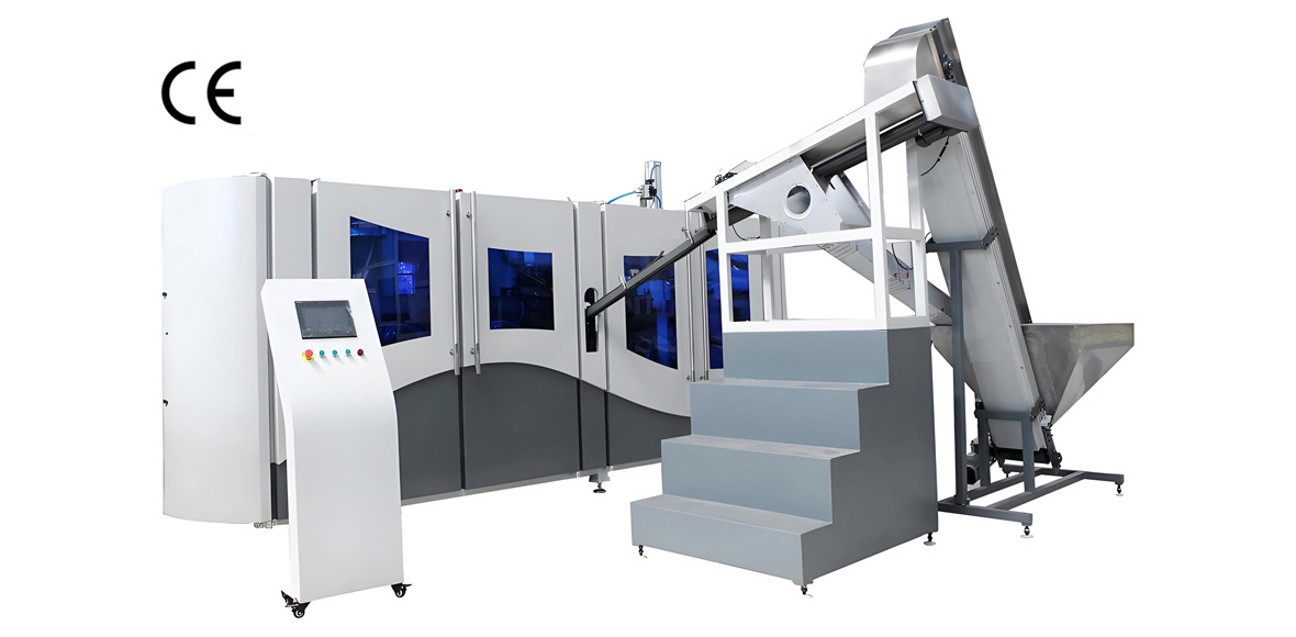
The FGX series is YuDa’s high-speed automatic stretch blow molding platform, built for lines from 8000 to 15000 BPH where the auxiliary system must be sized for continuous maximum output. The series is engineered around the unique cam-linking system that integrates mold-opening, mold-locking, and bottom mold-elevating into one coordinated movement, driven by a high-speed servo system that holds timing repeatable across millions of cycles. The ovens use the 38.1 mm heater pitch that saves more than 30 percent of electricity versus conventional ovens, and the whole line is modular so maintenance and changeovers are completed by swapping units rather than rebuilding sections.
For the auxiliary engineer, the key point is that the FGX class sets the demand for every utility branch above. At 12000 to 15000 BPH the high-pressure air demand, the mold cooling flow, and the oven power are all at their peak, so the receiver, chiller, and compressor must be specified from the top of the range, not the middle. The remote monitoring system also matters for auxiliaries: engineers at the China headquarters can read PLC data through a mobile connection, observe cycle behavior, and receive abnormal alerts, which includes utility faults such as a pressure dip or a chiller alarm fed back to the client site.
The table below lists representative parameters for the FGX high-speed class. These values are representative of the class and are confirmed per the buyer’s final bottle specification and cavity layout; the real fixed numbers are issued with the order configuration.
| Parameter | FGX High-Speed Class (representative) |
|---|---|
| Bottle volume range | 0.2 – 2.0 L (water, CSD, edible oil, daily-chem) |
| Line output | 8000 – 15000 BPH |
| Single blowing module speed | 2500 – 3000 BPH |
| Cavity configuration | multi-cavity modules, 6 / 8 / 10 cavities typical |
| Clamping system | servo cam-link integrating mold-open, lock, bottom-mold lift |
| Installed power (representative) | 45 – 95 kW by cavity count and oven length |
| High-pressure air | 3.5 – 4.0 MPa with air-recovery module (20–35% recovery) |
| Machine footprint (representative) | approx. 3.6 × 2.1 × 2.3 m per module (L × W × H) |
| Heating | 38.1 mm heater pitch, 30%+ energy saving vs conventional ovens |
| Control | PLC + HMI, SD-card recipe, remote PLC monitoring |
YuDa Standard-Speed and Semi-Automatic Series
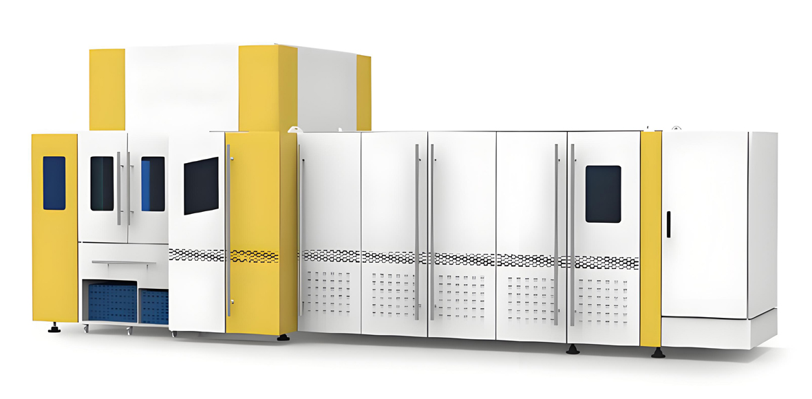
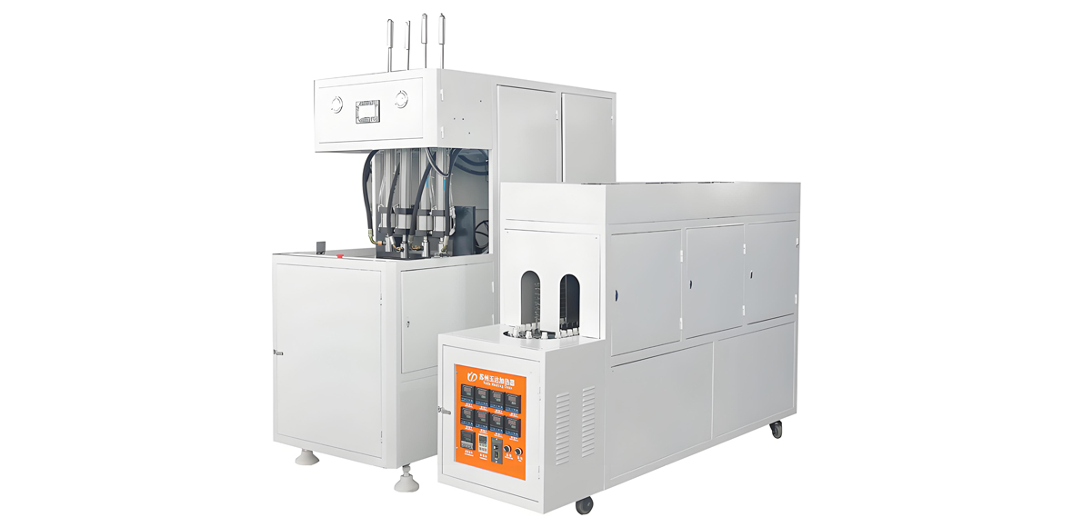
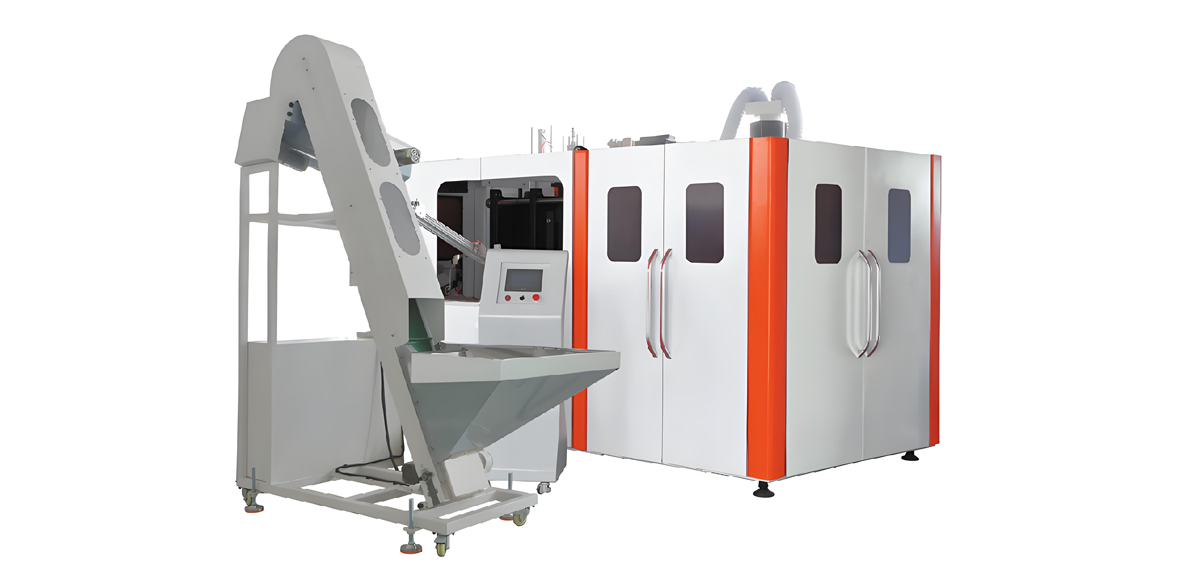
Not every plant needs 15000 BPH, and YuDa covers the mid and entry tiers with the standard-speed automatic series and the semi-automatic series. The standard-speed series covers 1000 to 7000 BPH with the same cam-linking and servo principles as the FGX class applied at a lower cavity count, making it the right choice for regional water, edible oil, daily-chemical, and condiment producers who need consistent automatic output without the peak-tier utility load. The semi-automatic series carries a lower procurement tier and suits small enterprises, laboratories, and flexible small-batch production where the operator loads preforms by hand.
The auxiliary load for these series is correspondingly lighter. A 2000 BPH semi-automatic line needs a much smaller compressor and receiver, a smaller chiller, and a simpler feeding system than a 12000 BPH automatic line, which is precisely why its procurement and operating tiers are lower. The trade is labor: a semi-automatic line needs an operator at the load and unload stations, so its effective capacity depends on staffing and on the consistency of manual handling, whereas an automatic line removes the operator from the cycle.
The table below compares the two series on the parameters that drive auxiliary sizing. As with the FGX table, the figures are representative of each class and are finalized per the confirmed bottle and cavity configuration.
| Parameter | Standard-Speed Automatic | Semi-Automatic |
|---|---|---|
| Output | 1000 – 7000 BPH | up to ~2000 BPH (manual load) |
| Bottle volume | 0.2 – 2.0 L | 0.1 – 2.0 L |
| Mold type | automatic multi-cavity | 2 – 4 cavity manual / semi |
| Installed power (representative) | 25 – 60 kW | 10 – 25 kW |
| High-pressure air | 3.5 – 4.0 MPa | 3.0 – 4.0 MPa |
| Footprint (representative) | approx. 2.8 × 1.8 × 2.1 m | approx. 1.6 × 0.9 × 2.0 m |
| Procurement tier | Medium – High | Low – Medium |
| Best fit | Mid-volume water, CSD, oil, daily-chem | Startups, labs, small batches |
Module 6: Bottle Conveying and Downstream Interface
Once the bottle is blown it must reach the next process without deformation, contamination, or pile-up, and that is the job of the conveying module. On most PET lines the preferred method is an air conveyor, a closed rail through which low-pressure air carries the bottle by its neck finish, because the bottle body never touches a surface and stays clean for filling. The air conveyor needs a blower sized for the required air velocity and pressure along the whole run, with extra capacity for vertical lifts and bends.
The neck finish decides the rail width and the bottle guide. Common finishes such as PCO 1810, PCO 1881, and 28 mm Alaska each have a defined neck diameter and support ring, and the conveyor and the downstream filler must share the same neck handling standard or bottles will jam at the interface. This is a frequent source of integration trouble when the blow line and the filling line are specified by different teams, so the neck finish should be locked before either line is ordered.
Buffering and accumulation protect the line from stoppages downstream. A buffer or accumulator between blowing and filling lets the blow machine keep running for a few minutes if the filler stops for a changeover, and a similar buffer protects the blow machine if the conveyor backs up. The buffer capacity is planned in minutes of line output, and the right amount depends on how often and how long the downstream stops; too little buffer and every filler stop becomes a blow stop, too much and floor space is wasted.
Interlocks keep the system safe and stable. A no-bottle condition at the filler inlet should signal the blow machine to slow or pause rather than flood the conveyor, and a conveyor full condition should do the same. These interlocks are part of the automation architecture but are planned here because they determine how the conveying module is sized and how it behaves under disturbance. Beat matching between the blow machine and the filler is the final parameter: the conveyor only works if both ends move at the same bottles per hour with the same surge behavior.
Module 7: Quality Inspection Equipment
A blow line makes thousands of bottles per hour, and no buyer wants a defective bottle to reach filling or, worse, the shelf. Inspection equipment splits into on-line systems built into the flow and off-line laboratory instruments used to qualify a bottle design and to audit production. Both are part of the auxiliary list because they sit around the blow machine and protect the output.
On-line inspection covers the measurements that catch a bad bottle before it leaves the module. Wall thickness is checked by a gauge or vision system, vertical load by a top-load station, burst pressure by a pressure test on a sample or every bottle, bottle volume by a fill-and-weigh check, verticality by a orientation check, neck finish dimensions by a gauging station, and clarity or haze by an optical check. Leak or light inspection rejects bottles with a hole or a thin spot, and a reject gate removes them from the flow automatically.
Off-line laboratory equipment qualifies the design and audits the run. Environmental stress crack resistance testing checks the bottle against stress cracking, thermal shrinkage testing measures how the bottle changes dimension with heat, and drop testing confirms the bottle survives handling. These tests are run on samples at startup and at a defined frequency during production, and their results are part of the release documentation for food and beverage customers.
The selection rule is simple: on-line inspection is Essential on any automatic line that feeds a filler, because manual inspection cannot keep pace with thousands of bottles per hour; off-line laboratory capability is Recommended for food, beverage, and pharmaceutical contact and Optional for non-critical industrial containers. Both should be specified together with the blow machine so the reject signals and the data feed into the same control and reporting system.
Module 8: Electrical and Automation Architecture
The electrical and automation module is the nervous system that makes the mechanical and utility modules behave as one line. It begins at the incoming supply, which must be stabilized because servo drives and ovens are sensitive to voltage sag and because a sag during a peak stroke can fault the line. A voltage stabilizer or, for unstable grids, an uninterruptible power supply sized to ride through the briefest outages protects the control and the oven recipe memory.
The control core is a PLC with an HMI for the operator, and the recipe management stores the full parameter set for each bottle on an SD card so a new format is launched by loading a verified recipe rather than tuning by trial. Remote monitoring extends this to the factory level: engineers at the China headquarters can read PLC data through a mobile connection and receive abnormal alerts, which turns fault diagnosis from reactive discovery into proactive guidance. For the auxiliary systems, this means a chiller alarm or an air-pressure dip is visible to support before it becomes a bottle defect.
Safety is built into the architecture rather than added later. Safety light curtains guard the operator access points, door interlocks prevent the machine from running with a guard open, and the emergency stop is wired to remove power from the moving and pressurized systems. The automation also carries the interlocks described in the conveying module, coordinating blow, conveyor, filler, and reject gate so the line degrades gracefully instead of colliding or flooding.
The配电 capacity must be sized from the sum of the blow machine, ovens, compressor, chiller, conveyor blowers, and auxiliary drives, expressed in kilovolt-amperes at the incoming panel. A common error is to size the panel from the blow machine nameplate alone and forget the compressor and chiller, which together can exceed the blow machine in starting load. The panel, the cable, and the stabilizer should all be specified from the full connected and starting load of the complete line.
Module 9: Plant Utilities and Compliance
The final module is the plant itself: the space, structure, services, and compliance that the line sits inside. A complete PET blow line needs a floor area that covers the blow machine, the ovens, the air system, the chiller, the conveyor run, the buffer, and the maintenance aisle, plus a clear height for the oven and any overhead services. The floor must carry the static and dynamic load of the machine and the receiver, and it should be level and clean for accurate machine alignment.
Ventilation and noise control are practical requirements that are easy to forget. The ovens and compressors release heat, so the plant needs ventilation or extraction to keep the ambient within the design range, because a hot room raises the chiller load and shortens lamp life. The high-pressure compressor is the loudest item on the line and should be placed in a separated or acoustically treated area so operators are not exposed to sustained high noise, which is both a comfort and a compliance issue.
Compliance covers utilities, waste, and food contact. Drainage must handle condensate from the air dryers and cooling blowdown, and any process water must meet the local discharge rules referenced by the applicable GB standards for the plant location. Fire protection follows the local building code for the machinery and electrical load. For the bottle itself, food-contact compliance is referenced by FDA in the United States and by EU 10/2011 in the European market, and the preform resin and any additive must carry the documentation that supports the intended market. These are referenced as plain standards here; the actual certificates are issued per material and per market.
Energy and environmental documentation is increasingly part of compliance too. Because the ovens are the largest steady consumer, the 30 percent plus saving from the 38.1 mm heater pitch is not only an operating-cost gain but also a defensible energy figure for plants that report consumption. The air-recovery module and the servo drives further lower the per-1000-bottles energy number, and that figure should be tracked from commissioning so the plant can demonstrate the trend.
Complete Auxiliary Equipment Checklist
The consolidated checklist below groups every auxiliary item into Essential, Recommended, and Optional tiers, with the key selection parameter and a priority rating from Low to High. Use it as the bill of materials backbone: Essential items are required for the line to run and to be food-safe, Recommended items protect output and quality at scale, and Optional items add capability or convenience. Priority reflects how strongly the item affects whether the line meets its bottles-per-hour and quality targets.
| Tier | Item | Key selection parameter | Priority |
|---|---|---|---|
| Essential | Preform hopper | 10–15 min buffer of BPH × mass | High |
| Essential | Preform elevator / feeder | pcs/min > oven demand × 1.10 | High |
| Essential | Sorter and transfer | orientation accuracy, oven pitch | High |
| Essential | High-pressure compressor | 3.5–4.0 MPa, Nm³/min from BPH | High |
| Essential | High-pressure receiver | volume from per-bottle air × BPH | High |
| Essential | Precision filter and dryer | oil ≤0.01 mg/m³, dew point | High |
| Essential | Low-pressure air loop | 0.6–0.8 MPa for pneumatics | Medium |
| Essential | Mold cooling chiller | 7–12 °C, L/min per cavity | High |
| Essential | Blow mold set | Al body, SS base, polished cavity | High |
| Essential | Electrical panel and stabilizer | kVA from full connected load | High |
| Essential | PLC + HMI + safety interlocks | recipe management, light curtain | High |
| Recommended | Metal detector | aperture by preform diameter | High |
| Recommended | Dust / static removal | airknife flow, ionizer | Medium |
| Recommended | Air recovery module | 20–35% recovery of HP air | High |
| Recommended | Secondary cooling loop | 15–20 °C for frame and oven | Medium |
| Recommended | Air conveyor and buffer | neck finish, minutes of buffer | High |
| Recommended | On-line inspection | wall, top-load, burst, neck | High |
| Recommended | Remote monitoring | PLC data, mobile alerts | Medium |
| Recommended | Water pretreatment | filter, softener or RO | Medium |
| Optional | Preform tempering | entry temperature window | Low |
| Optional | Off-line lab instruments | ESCR, shrinkage, drop test | Medium |
| Optional | UPS for control | ride-through for grid sag | Low |
| Optional | Spare lamp and mold kit | stock for scheduled rotation | Medium |
Three-Tier Line Configuration Examples
The three examples below show how the auxiliary list scales with the line. The small example is a semi-automatic or low automatic line near 2000 BPH, the medium example is an automatic line near 6000 BPH, and the large example is a high-speed line at or above 12000 BPH. Energy is expressed as kilowatt-hours per 1000 bottles, and the investment tier uses the Low, Medium, High, Very High, and Premium scale rather than a currency figure.
Small line (~2000 BPH)
| Subsystem | Configuration |
|---|---|
| Blow machine | Semi-automatic or entry automatic, up to ~2000 BPH |
| High-pressure air | piston compressor, receiver 1.0–2.0 m³, 3.0–4.0 MPa |
| Cooling | compact chiller, mold loop 7–12 °C |
| Feeding | hopper, manual or basic elevator, sorter |
| Conveying | short belt or basic air rail, small buffer |
| Energy | higher kWh per 1000 bottles (manual, smaller scale) |
| Investment tier | Low – Medium |
Medium line (~6000 BPH)
| Subsystem | Configuration |
|---|---|
| Blow machine | Standard-speed automatic, 1000–7000 BPH class |
| High-pressure air | piston compressor, receiver 2.0–3.0 m³, air recovery advised |
| Cooling | chiller mold loop + secondary loop, water pretreatment |
| Feeding | automatic elevator, sorter, metal detector, dust removal |
| Conveying | air conveyor, buffer minutes, filler interlock |
| Inspection | on-line wall, top-load, burst, neck gauge |
| Energy | moderate kWh per 1000 bottles |
| Investment tier | Medium – High |
Large line (≥12000 BPH)
| Subsystem | Configuration |
|---|---|
| Blow machine | FGX high-speed, 8000–15000 BPH, multi-cavity modules |
| High-pressure air | multiple piston compressors, receiver 3.0–8.0 m³, air recovery |
| Cooling | large chiller, dual loops, plate exchanger, pretreatment |
| Feeding | high-capacity elevator, sorter, metal detector, tempering |
| Conveying | full air conveyor, large buffer, tight filler beat match |
| Inspection | full on-line suite plus off-line lab |
| Automation | PLC + HMI, remote monitoring, UPS, full interlocks |
| Energy | lowest kWh per 1000 bottles at scale, 38.1 mm oven saving |
| Investment tier | Very High – Premium |
Requirement-to-Model Selection Guide
This table maps a buyer’s stated requirement to a recommended YuDa model and the auxiliary combination that supports it. The logic is driven by three inputs: target bottles per hour, bottle volume, and bottle type. Carbonated and hot-fill bottles push both the blow pressure and the inspection requirement upward, while still water at moderate volume is the lightest case. The auxiliary column lists the minimum Essential set plus the Recommended items that the speed tier justifies.
| Target BPH | Bottle volume | Bottle type | Recommended model | Auxiliary combination |
|---|---|---|---|---|
| up to ~2000 | 0.1 – 2.0 L | water, daily-chem | Semi-automatic series | Essential set, small compressor and chiller |
| 1000 – 3000 | 0.2 – 2.0 L | water, oil, condiment | Standard-speed automatic | Essential set, metal detector, basic conveyor |
| 3000 – 7000 | 0.2 – 2.0 L | CSD, water, oil | Standard-speed automatic (higher cavity) | Essential set, air recovery, dual-loop cooling, on-line inspection |
| 8000 – 12000 | 0.2 – 2.0 L | CSD, water | FGX high-speed | Essential set, multi-compressor, large receiver, recovery, full inspection, remote monitoring |
| ≥12000 | 0.2 – 2.0 L | CSD, water, export | FGX high-speed, multi-module | Full Essential + Recommended, off-line lab, UPS, pretreatment |
Common Configuration Mistakes to Avoid
The same few mistakes appear in almost every underperforming PET blow line, and each of them traces back to sizing an auxiliary from an average instead of from a peak or from a guess instead of from a parameter. Avoiding them is cheaper than fixing them after commissioning.
- Compressor sized from average demand. Blow air is consumed in peaks at each stroke, so the compressor and receiver must cover the peak, not the mean. Sizing from the average leaves the line starved at the busiest moment and produces thin or uneven bottles.
- Receiver too small. An undersized receiver lets pressure dip between compressor responses, and that dip translates directly into wall-thickness variation that no mold adjustment corrects. Size the receiver from per-bottle air volume times bottles per hour with a buffering factor.
- Chiller tonnage too low. A chiller sized for a short trial runs out of capacity after an hour of continuous blowing as molds heat up. Size from the steady thermal load of the full cavity count, not from a brief test.
- Conveyor and filler beat mismatch. If the air conveyor or the downstream filler moves at a different bottles-per-hour than the blow machine, bottles accumulate or starve. Lock the neck finish and the节拍 before ordering either line.
- Ignoring air filtration grade. Skipping precision filtration puts oil aerosol onto the food-contact bottle interior, a direct compliance failure. The oil content must be held at or below 0.01 mg per cubic meter for a food line.
- Two loops mixed into one. Feeding the mold and the machine frame from a single cooling loop forces over-cooling and wastes energy while still risking mold temperature. Keep the 7–12 °C mold loop separate from the 15–20 °C loop.
- Panel sized from blow machine only. Forgetting the compressor and chiller starting load leads to voltage sag and nuisance trips. Size the incoming panel, cable, and stabilizer from the full connected and starting load.
Commissioning and SAT Checklist
Site acceptance is where the auxiliary list is proven. The line should pass a structured sequence before it is released to production: an empty-run check, a single-cavity verification, a continuous stability run, and a quality and energy verification. Each step has a pass criterion that the buyer and the factory both record.
| Step | What is checked | Pass criterion |
|---|---|---|
| No-load run | All auxiliaries start, interlocks, alarms | No fault; pressure and temperature reach setpoint |
| Single-cavity trial | One cavity blown, wall and neck measured | Wall within tolerance; neck finish in spec |
| 4-hour stability | Continuous run at target BPH | Stable BPH; pressure and temp held |
| Quality check | Top-load, burst, volume, haze | Meets bottle specification |
| Energy check | kWh per 1000 bottles measured | Within planned band for the tier |
| Noise check | Compressor area sound level | Within local exposure limit |
Application Industries Served by YuDa
YuDa blow machines and their auxiliary lines serve the full range of PET container markets, and the auxiliary list shifts with the product. For drinking water the line is the lightest case: still bottles, standard necks, moderate pressure, and a focus on throughput and energy. For carbonated beverages the blow pressure reaches the top of the 3.5 to 4.0 MPa range, the petaloid base and burst pressure become critical, and air recovery plus full inspection are strongly recommended.
For edible oil and cooking oil the bottles are larger and the preform heavier, which raises the oven load and the mold cooling demand, so the chiller and oven must be sized for the bigger surface area. For daily-chemical and detergent bottles the shapes are often non-standard with handles or asymmetry, which drives more mold cavities of custom design and more careful conveyor handling. For condiments, sauces, and similar products the line must handle a range of volumes and neck finishes, which makes quick-change tooling and recipe management more valuable.
Across all of these, the common thread is that the auxiliary system determines whether the machine’s rated bottles per hour is actually achieved on the buyer’s bottle, in the buyer’s climate, with the buyer’s water and power. The same FGX high-speed machine can reach 15000 BPH on one site and struggle on another purely because the air, water, or feeding support was specified differently. That is why this article treats the auxiliary list as the real scope of the project, not an afterthought.
Service and Support from YuDa
YuDa, as a Wanplas factory, backs each line with the group’s shared service commitments so that the auxiliary system is supported for its whole life, not only at handover. Before shipment the line is run and tested at the factory, including the blow machine together with its key auxiliaries where the scope allows, so that utility faults are found in the workshop rather than at the buyer’s site. This pre-shipment testing is the first line of defense against the configuration mistakes listed above.
After arrival, engineers perform installation and commissioning, aligning the machine, connecting the utility branches, and running the SAT sequence with the buyer. The shared Wanplas policy provides USD 500 free parts per year, which covers wear items such as lamps, seals, and minor components without a separate claim process, and damaged parts within warranty are replaced. Operator and mold training teach the line team to run recipes, perform changeovers, and maintain the auxiliaries, while remote monitoring lets YuDa engineers read PLC data and guide correction when an abnormal condition appears.
The open factory policy welcomes customer visits for audit and for sample trial runs, so a buyer can validate the machine and its auxiliaries on real preforms before committing to a full configuration. For the auxiliary scope this means the compressor, chiller, conveyor, and inspection can all be seen running as a system, which is the most reliable way to confirm that nothing on the checklist has been missed.
Frequently Asked Questions
What auxiliary equipment is absolutely required to run a PET blow machine?
The Essential set is a preform hopper and feeder, a sorter, a high-pressure compressor with receiver, precision filtration and drying, a mold cooling chiller, the blow mold set, a stabilized electrical panel, and the PLC with safety interlocks. Without any one of these the line cannot produce food-safe bottles at its rated speed. Feeding, air, cooling, mold, and control are the five non-negotiable branches.
Why is the high-pressure air system called the most critical auxiliary?
Because it forms the bottle and sets the production ceiling. Each bottle consumes a fixed volume of 3.5 to 4.0 MPa air, so if the compressor, receiver, or filtration cannot supply that volume at stable pressure, the whole line slows or produces thin-wall defects. Low-pressure air only moves parts; high-pressure air makes the bottle, which is why this branch is planned first after the machine itself.
How large should the high-pressure receiver be?
The receiver volume comes from the single-bottle air volume multiplied by the target bottles per hour and a buffering factor that covers the compressor reaction time. Representative figures run from about 1.0 to 2.0 cubic meters near 2000 BPH up to 3.0 to 8.0 cubic meters at 12000 BPH and above. A receiver that is too small causes pressure dips that show up directly as uneven bottle walls.
Do I need air recovery on a smaller line?
Air recovery is Recommended from the medium tier upward because it returns 20 to 35 percent of the high-pressure air and reduces both compressor size and energy load. On a small semi-automatic line it is Optional, but on any automatic line above a few thousand bottles per hour the recovery percentage quickly justifies the module through a smaller compressor and lower operating energy.
What cooling water temperature should the mold loop use?
The mold loop should run chilled water at roughly 7 to 12 degrees Celsius, while a separate loop at 15 to 20 degrees Celsius serves the machine frame and oven. Mixing the two forces over-cooling and can still leave the mold too warm, so the mold loop must be independent and sized in liters per minute per cavity for the full cavity count.
Which inspection equipment is Essential versus Optional?
On-line inspection is Essential on any automatic line that feeds a filler, because manual checking cannot match thousands of bottles per hour; it covers wall thickness, top-load, burst pressure, volume, verticality, neck dimensions, and clarity. Off-line laboratory instruments for stress cracking, thermal shrinkage, and drop testing are Recommended for food and beverage contact and Optional for non-critical industrial containers.
How do I avoid the most common configuration mistakes?
Size every auxiliary from the peak demand and from a parameter, never from an average or a guess: compressor and receiver from peak air per bottle, chiller from steady cavity load, conveyor and filler from the same bottles-per-hour and neck finish, and the electrical panel from the full connected and starting load including compressor and chiller. Hold air oil content at or below 0.01 mg per cubic meter for food contact.
What does YuDa provide after the line is installed?
YuDa provides pre-shipment testing, on-site installation and commissioning, the Wanplas shared policy of USD 500 free parts per year, warranty replacement of damaged parts, operator and mold training, remote PLC monitoring with mobile alerts, and an open factory policy for audit and sample trials. The auxiliary systems are supported as part of the same line, not as separate orphaned equipment.
Conclusion and Call to Action
A complete PET bottle blowing production line is far more than the stretch blow molding machine, and the difference between a line that hits its rated bottles per hour and one that does not is almost always in the auxiliary scope. The list in this article covers preform handling, the high-pressure air system that forms the bottle and sets the ceiling, the cooling water that sets the cycle floor, the infrared oven that conditions the preform, the molds that define the bottle, the conveying that protects it downstream, the inspection that guards quality, the electrical and automation that coordinate everything, and the plant utilities and compliance that contain it all.
YuDa, a Wanplas factory with 20+ years of experience, equipment in 60+ countries, a top 2 position among Chinese PET blow machine manufacturers, and 20+ patents, builds the FGX high-speed, standard-speed automatic, and semi-automatic series that these auxiliaries support, and backs them with pre-shipment testing, installation and commissioning, USD 500 free parts per year, training, remote monitoring, and an open factory policy. The right next step is to send your target bottles per hour, bottle volume, bottle type, and neck finish, and the YuDa team will return a complete, parameter-backed auxiliary list and a tailored line configuration for your plant, with an invitation to visit the factory and run your preforms on the actual system before you commit.