Introduction: Why Capacity and Floor Area Must Be Planned Together
YuDa, a Wanplas factory, has supplied PET bottle blow molding machines to beverage, edible oil, dairy, and personal care producers in more than 60 countries for over 20 years, and during that time the single most common planning mistake we see in new bottling projects is treating production capacity and factory floor area as two separate problems. A buyer selects a blowing rate in bottles per hour, signs the order, and only later discovers that the machine, the filler, the conveyor buffer, the air compressor, the preform silo, the packing island, and the finished-goods corridor cannot physically fit inside the available hall, or fit only by eliminating the buffer space that the line needs to run without constant stoppages. Large-scale PET bottle mass production is a systems problem, and the two variables that define the system are throughput, measured in bottles per hour, and occupied area, measured in square meters. This article explains how to match them deliberately rather than by accident.
Over the next sections we walk through the complete mass-production line for PET bottles, from preform feeding and reheat through stretch blow molding, filling, capping, labeling, and packing, and we show how each stage consumes floor area in proportion to the rate it must sustain. We then present reference tables that map a target output tier to a realistic total plant area, to per-machine footprints, to utility demand in kilowatts and cubic meters per minute, and to the number of operators required per shift. Throughout, we reference genuine YuDa PET bottle line configurations, including the FGX high-speed series and the Linear Blowing-Filling-Capping CombiBlock, so that the planning numbers connect to equipment that actually exists. By the end, an engineer or a plant manager should be able to take a single number, the desired bottles per hour, and derive a credible first-cut floor area, a credible utility budget, and a short list of candidate YuDa machines.
The method described here applies whether you are building a greenfield bottling plant, expanding an existing hall, or replacing an older generation of machinery. It is deliberately conservative: we reserve circulation aisles, maintenance clearance, quality-control sampling space, and a realistic buffer between blowing and filling. Cutting those reserves to lower the quoted area almost always raises the real cost later through downtime, unsafe aisles, and impossible maintenance access. Plan the area for the running line, not for the brochure photo.
Why Production Capacity and Plant Area Must Be Matched
Production capacity and factory area are coupled because every unit of throughput requires a physical station that occupies space, and most stations also require adjacent buffer space so that a temporary stoppage at one station does not cascade into a total line stoppage. A PET bottle line is only as fast as its slowest coupled stage, and coupling stages too tightly to save floor area makes the whole line fragile. The art of capacity-and-area matching is to give each stage enough room to reach its rated speed while keeping the total building envelope within budget.
Three mechanisms link capacity to area. First, the blowing machine footprint grows with cavity count, because more cavities mean a wider mold and a longer oven, and a wider mold means a larger clamping platen and a larger machine frame. A four-cavity machine does not occupy four times the area of a one-cavity machine, but a ten-cavity machine is meaningfully larger than a four-cavity one. Second, the filling and capping island scales with the number of filling valves, which in turn scales with bottles per hour, and that island needs straight conveyor length for bottle stabilization and for accumulator buffer. Third, downstream packing, palletizing, and finished-goods staging scale almost linearly with throughput, because every bottle that leaves the capper must still be wrapped, cased, or palletized and then stored before shipment.
A useful planning rule is that the blowing and filling core typically occupies only 35 percent to 45 percent of the total hall area in a large-scale plant. The remaining 55 percent to 65 percent is buffer, utilities, packing, warehouse staging, aisles, and quality control. Projects that budget area only for the machines themselves almost always underestimate the building by a wide margin. The matrix later in this article allocates area across all these functions so the estimate reflects the real plant rather than the machine list.
Energy and labor also move with capacity, and they indirectly affect area because compressors, chillers, and electrical rooms must be housed. A high-output line rated at 15,000 bottles per hour or more needs a high-pressure air system and a low-pressure aux system, plus a chiller and a cooling tower or dry cooler, and those support systems can themselves require several hundred square meters of dedicated plant room. Ignoring the utility plant is the second most common underestimation after ignoring buffer space.
Line Bottleneck Breakdown: From Preform to Pallet
To match area to capacity, first decompose the line into its stages and identify which stage sets the pace. In two-step PET bottle mass production, the sequence is preform supply, preform reheating, stretch blow molding, air conveyance, filling, capping, leak and vision inspection, labeling, packing, and palletizing. Each stage has a rated capacity, an installed footprint, and a buffer requirement.
Preform Supply and Reheat
Preforms arrive in gaylord boxes or silos and are oriented and fed into the blow machine oven. The reheat oven is the first significant area consumer after the clamp unit, because polyethylene terephthalate must be conditioned in multiple infrared zones to a precise temperature profile before stretching. The oven length scales with the number of heating rows and with cavity count. A compact reheat oven for a four-cavity machine is short; a wide oven for an eight-cavity or ten-cavity machine is substantially longer and needs front clearance for loader service. The YuDa energy-saving design reduces oven length pressure by minimizing the heater pitch to 38.1 millimeters, which shortens the oven and trims electricity use by more than 30 percent compared with conventional heating ovens, a real area and power advantage at high cavity counts.
Stretch Blow Molding
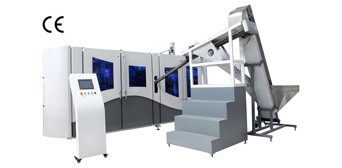
The blow station converts the conditioned preform into a biaxially oriented bottle. Output equals cavity count multiplied by single-cavity cycles per hour. YuDa FGX high-speed machines deliver roughly 2,500 to 3,000 bottles per hour per cavity, so a four-cavity configuration reaches about 10,000 to 12,000 bottles per hour and a six-cavity configuration reaches the upper high-speed band near 15,000 bottles per hour and beyond. The clamp frame, the servo cam-linking system that integrates mold opening, mold locking, and bottom-mold elevation in one movement, and the oven together define the machine envelope. This is the anchor of the line layout.
Filling, Capping, and Inspection
Bottles travel by air conveyor to the filler, where they are filled, capped, and checked. Filler valve count sets capacity, and the filler plus capper plus empty-bottle and full-bottle accumulators form a long island that needs straight conveyor runs. Accumulator tables are not optional luxuries; they let the blower keep running for minutes if the filler pauses, and they let the filler keep running if the blower pauses. The area for accumulators is frequently the difference between a line that sustains rated output and one that averages far below it. Leak testers and vision systems sit on this island and add modest width but meaningful length.
Labeling, Packing, and Palletizing
Downstream of inspection, bottles are labeled, then packed into shrink film or cases, then palletized and wrapped. These stations scale with throughput almost linearly and together can occupy as much area as the blow-and-fill core. Packing and palletizing also generate the finished-goods buffer that must be staged for shipment, and that staging area is part of the plant envelope even though it is not machinery. For large-scale production above 10,000 bottles per hour, the downstream packing and warehouse buffer often exceeds the blowing machine footprint several times over.
YuDa FGX High-Speed PET Blow Molding Lines
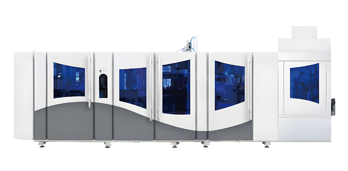
The FGX series is YuDa’s high-speed, fully automatic stretch blow molding family, engineered for large-scale PET bottle mass production in the 8,000 to 15,000 bottles per hour band and beyond. Its defining features are a unique cam-linking mechanism that combines mold opening, mold locking, and bottom-mold elevation into a single servo-driven movement, a high-speed servo driving system, a remote monitoring system that lets engineers at the YuDa headquarters read the machine PLC data on a mobile device and push abnormal-condition feedback to the customer site, and a modularized design that simplifies maintenance and mold changeovers. The minimized 38.1 millimeter heater distance is the centerpiece of the energy-saving claim, cutting oven electricity by more than 30 percent versus conventional ovens.
Below is a representative specification set for FGX configurations expressed by cavity count. Exact figures vary with bottle shape, gram weight, neck finish, and local utility conditions, but the values in the table are typical engineering starting points for planning. When you send YuDa your bottle drawing and target output, the factory returns a confirmed configuration and a confirmed footprint.
| Model Configuration | Cavities | Rated Output (BPH) | Typical Footprint (L x W, m) | Installed Power (kW) | High-Pressure Air (m3/min at 30 bar) | Cost Index (100 = baseline) |
|---|---|---|---|---|---|---|
| FGX-4 | 4 | 10,000 to 12,000 | 3.6 x 1.8 | 48 | 2.0 | 100 |
| FGX-6 | 6 | 14,000 to 16,000 | 4.0 x 2.0 | 68 | 3.0 | 145 |
| FGX-8 | 8 | 19,000 to 22,000 | 4.8 x 2.2 | 92 | 4.2 | 195 |
| FGX-10 | 10 | 24,000 to 28,000 | 5.4 x 2.4 | 118 | 5.4 | 245 |
The FGX-4 is the entry point into high-speed mass production and is the configuration most often paired with a medium rotary filler for a regional water or edible-oil brand. The FGX-6 sits at the top of the classic high-speed band and is a common choice where floor width is limited but output must clear 14,000 bottles per hour. The FGX-8 and FGX-10 are for dedicated large-scale plants and require the wider utility and packing envelope described later. All configurations share the modular frame, so a plant that grows from FGX-4 to FGX-8 can reuse tooling philosophy, spare modules, and operator training, which protects the original area and labor plan as capacity scales.
Because the FGX ovens are shortened by the tight heater pitch, the machine envelope is smaller than that of a conventional oven design at the same cavity count. That shortened envelope is precisely the capacity-and-area advantage a plant designer cares about: it returns floor area to buffer and packing without sacrificing bottles per hour. For a 10,000 bottles per hour line, the recovered oven length can be several meters, enough for an extra accumulator or a safer maintenance aisle.
YuDa Linear BFC CombiBlock and BFC Machines
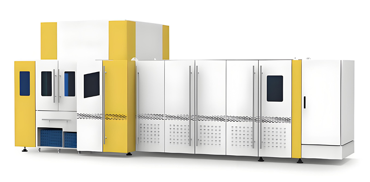
Where the tightest area budget applies, YuDa offers the Linear Blowing-Filling-Capping CombiBlock and the Bottle Blow-Filling-Capping machine, which integrate blowing, filling, and capping into a single compact block. The CombiBlock is specialized in the mini linear BFC format: it is compact, simple, and easy to operate, and it saves plant area by eliminating the separate blow-to-fill air conveyor and the associated accumulator. For a given output, a CombiBlock typically occupies 25 percent to 35 percent less floor area than a discrete blower plus filler plus capper laid out in series, at the cost of somewhat less flexibility for changeovers between very different bottle families.
| Model | Process | Rated Output (BPH) | Typical Footprint (L x W, m) | Installed Power (kW) | Area Saving Versus Discrete Line | Cost Index (100 = baseline FGX-4) |
|---|---|---|---|---|---|---|
| Linear BFC CombiBlock (mini) | Blow + Fill + Cap in one block | 2,000 to 6,000 | 6.0 x 2.2 | 40 | 25 percent to 35 percent | 95 |
| BFC Machine (water) | Blow, fill drinking water, cap in one process | 6,000 to 12,000 | 9.0 x 2.6 | 62 | 20 percent to 30 percent | 130 |
The mini Linear BFC CombiBlock is especially attractive for a startup bottler or for a satellite filling line inside a larger factory, because the reduced area and simplified material flow lower both the civil-build cost and the commissioning time. The water BFC machine is aimed at bottled-water plants that want to minimize oxidation and transfer points between blowing and filling, which also improves hygiene and reduces the clean-area envelope. Both machines retain the YuDa remote-monitoring and modular-maintenance philosophy, so service planning is consistent with the FGX family even though the layout is integrated.
When area is the binding constraint, the decision is rarely “CombiBlock versus FGX” on performance alone. It is CombiBlock when the building is fixed and output is moderate, and discrete FGX plus rotary filler when output must climb past 15,000 bottles per hour or when many bottle families must be run on one line. The selection table near the end of this article makes that trade explicit.
Floor Area Layout and Cell Design Principles
A good PET bottling layout follows a straight or gently L-shaped flow from preform intake to finished pallet outfeed, with the heavy utility plant placed along one wall and the packing and warehouse buffer at the opposite end. The objective is to minimize bottle travel, keep aisles wide enough for a pallet truck, and leave service clearance on at least two sides of every machine. A common error is to line machines against walls with no rear access, which makes mold changes and oven service slow and sometimes unsafe.
Process Flow and Aisle Width
Reserve a minimum main aisle of 2.0 meters for pallet-truck and forklift movement, and a minimum service aisle of 1.0 meter behind blowing and filling equipment. The blow machine needs front clearance equal to roughly its own depth for preform loader and mold cart access. The filler island needs straight conveyor of several meters on both sides for empty and full bottle accumulators. Labeling and packing need a clear linear run, not a cramped corner, because film wrappers and case packers have infeed and outfeed zones that are easy to underestimate.
Utility Plant Placement
High-pressure and low-pressure compressors, the chiller, the cooling tower or dry cooler, and the electrical switchboard should be grouped in a dedicated utility room or plant strip along one wall, not scattered through the production hall. This keeps noise and heat out of the bottling area and concentrates the area that must be structurally reinforced for vibration. For a 15,000 bottles per hour line, budget a utility strip of roughly 8 to 12 meters by 4 to 6 meters, or about 40 to 70 square meters, depending on whether the chiller is indoors.
Buffer and Quality-Control Reserves
Preform buffer, empty-bottle accumulator, full-bottle accumulator, and finished-goods staging are not waste; they are the shock absorbers of the line. A practical reserve is two to five minutes of running buffer at the blow-to-fill interface and at the fill-to-pack interface. At 15,000 bottles per hour, five minutes is 1,250 bottles, which in 500 milliliter format is a meaningful conveyor length. The matrix below turns these reserves into area numbers so the plan reflects a line that actually runs.
Machine Footprint and Cell Reference Tables
The tables in this section convert machine footprints into cell areas by adding the service clearance and buffer that a realistic installation requires. Cell area is what you should use for building estimation, not bare machine footprint.
| Station | Bare Footprint (sq m) | Recommended Cell Area (sq m) | Notes |
|---|---|---|---|
| FGX-4 blow molder | 6.5 | 16 to 20 | Front loader and rear mold cart access |
| FGX-6 blow molder | 8.0 | 20 to 24 | Wider oven service aisle |
| FGX-8 blow molder | 10.6 | 26 to 30 | Needs dedicated mold-change space |
| FGX-10 blow molder | 13.0 | 32 to 38 | Plan rear access from day one |
| Rotary filler and capper island | 10 to 18 | 30 to 50 | Includes two accumulators |
| Labeler and vision inspection | 4 to 8 | 12 to 18 | Linear infeed run required |
| Film wrapper and case packer | 6 to 12 | 20 to 35 | Outfeed to palletizer |
| Palletizer and stretch wrapper | 6 to 10 | 18 to 28 | Leads to finished-goods buffer |
| Layout Element | Small Line (to 5,000 BPH) | Medium Line (5,000 to 12,000 BPH) | Large Line (12,000 to 28,000 BPH) |
|---|---|---|---|
| Blow plus fill core cell | 60 to 90 sq m | 110 to 170 sq m | 200 to 320 sq m |
| Utilities and electrical | 20 to 35 sq m | 40 to 70 sq m | 70 to 120 sq m |
| Packing and palletizing | 40 to 70 sq m | 90 to 150 sq m | 160 to 280 sq m |
| Preform and finished buffer | 50 to 90 sq m | 120 to 220 sq m | 250 to 450 sq m |
| Aisles and QC sampling | 30 to 50 sq m | 70 to 120 sq m | 140 to 240 sq m |
Adding the rows for a large line gives a total plant envelope in the region of 820 to 1,410 square meters for the production and near-line storage area alone, before the bulk warehouse that holds days of finished product. That order of magnitude is the number a civil engineer needs, and it is far larger than the machine footprints suggest. The next section consolidates these into a single capacity-versus-area matrix.
Capacity Versus Factory Area Matching Matrix
The matrix below is the planning centerpiece. It maps a target output tier to a recommended total near-line area, a recommended YuDa machine set, and a cost index where 100 equals the FGX-4 baseline configuration. The area figures cover blowing, filling, packing, utilities, buffer, and aisles, but exclude the distant bulk warehouse. Use the medium of each band for early budgeting and the high end when bottle sizes vary or changeovers are frequent.
| Output Tier (BPH) | Recommended YuDa Set | Near-Line Area (sq m) | Power (kW) | Operators per Shift | Cost Index | Cost Tier |
|---|---|---|---|---|---|---|
| 2,000 | Linear BFC CombiBlock (mini) | 220 to 320 | 40 | 3 | 95 | Low |
| 5,000 | FGX-4 plus rotary filler | 320 to 460 | 60 | 4 | 110 | Medium |
| 10,000 | FGX-4 or FGX-6 plus rotary filler | 480 to 680 | 90 | 5 | 145 | Medium |
| 15,000 | FGX-6 plus rotary filler | 650 to 920 | 130 | 6 | 175 | High |
| 22,000 | FGX-8 plus high-speed filler | 900 to 1,250 | 190 | 7 | 215 | High |
| 28,000 | FGX-10 plus high-speed filler | 1,150 to 1,550 | 240 | 8 | 255 | Very High |
The cost index is a relative equipment-and-core-installation indicator, not a quoted price; it lets a planner compare configurations on a common scale where the FGX-4 baseline equals 100. A 28,000 bottles per hour line is therefore roughly two and a half times the baseline equipment investment, before building and warehouse. The cost tier labels, Low through Very High, give a plain-language band that procurement teams can use without exposing a currency figure. Real offers depend on bottle specification, filling product, voltage, and destination, and YuDa quotes those on request.
Note the non-linear area growth. Doubling output from 5,000 to 10,000 bottles per hour does not double the area, because buffer and utilities scale sub-linearly once a plant crosses into the medium band. But jumping from 15,000 to 28,000 bottles per hour adds both a larger blow molder and a materially larger packing and warehouse buffer, so area grows faster again. The matrix captures this shape better than a simple per-bottle rule.
Utilities and Headcount Planning
Capacity drives utility demand, and utility demand drives the size of the plant room and the incoming electrical service. The table below gives typical planning figures for a two-step line at several output tiers. High-pressure air is the dominant consumable for stretch blow molding; low-pressure air serves conveyors and actuators; cooling water serves the compressor after-cooler, the chiller, and the mold-temperature circuit.
| Output Tier (BPH) | Electricity (kW installed) | High-Pressure Air (m3/min at 30 bar) | Low-Pressure Air (m3/min at 7 bar) | Cooling Water (m3/h) | Compressed-Air Plant Area (sq m) |
|---|---|---|---|---|---|
| 2,000 | 40 | 0.9 | 1.0 | 3 | 15 to 25 |
| 5,000 | 60 | 2.0 | 1.5 | 6 | 25 to 35 |
| 10,000 | 90 | 3.2 | 2.2 | 10 | 35 to 50 |
| 15,000 | 130 | 4.6 | 3.0 | 15 | 50 to 70 |
| 22,000 | 190 | 6.4 | 4.0 | 22 | 70 to 95 |
| 28,000 | 240 | 8.0 | 5.0 | 28 | 90 to 120 |
| Role | Small Line (to 5,000 BPH) | Medium Line (5,000 to 12,000 BPH) | Large Line (12,000 to 28,000 BPH) |
|---|---|---|---|
| Line operator | 2 | 3 | 4 |
| Filler and capper technician | 0 to 1 | 1 | 1 to 2 |
| Packing and palletizing | 1 | 1 to 2 | 2 to 3 |
| Quality control and sampling | 0 to 1 | 1 | 1 to 2 |
| Shift total | 3 to 4 | 4 to 6 | 6 to 8 |
Headcount scales gently with capacity because a well-automated YuDa line runs with few hands once it is stabilized; the larger share of added labor at high output goes to packing and quality control rather than to the machines themselves. The utilities, however, scale almost directly with bottles per hour, which is why the compressed-air plant area and the incoming transformer rating are the items that most often surprise a first-time bottling investor. Plan the electrical room and the compressor house from the utility table, not from the machine nameplate alone.
Selection Guide: Matching Output Target to Floor Area
Use the following decision table to move from a business requirement to a candidate YuDa configuration. The logic is: fix the target bottles per hour and the largest bottle family, check the available near-line area against the matrix, then choose the machine set whose footprint and utility demand fit the building. If the building is fixed and small, prefer the CombiBlock; if output must grow, prefer a discrete FGX plus rotary filler so the line can be upgraded cavity by cavity.
| If your requirement is… | Recommended YuDa configuration | Why |
|---|---|---|
| Up to 2,000 BPH, very tight area, one bottle family | Linear BFC CombiBlock (mini) | Integrated blow-fill-cap saves 25 to 35 percent area; simplest flow |
| 3,000 to 6,000 BPH, moderate area, water focus | BFC Machine (water) | One-process blowing and filling; good hygiene, lower clean-area envelope |
| 5,000 to 10,000 BPH, room to grow | FGX-4 plus rotary filler | Baseline high-speed; upgradable and widely supported |
| 12,000 to 16,000 BPH, standard water or CSD | FGX-6 plus rotary filler | Top of classic high-speed band; compact oven through 38.1 mm pitch |
| 18,000 to 24,000 BPH, multiple SKUs | FGX-8 plus high-speed filler | Headroom for changeovers; modular frame eases service |
| 24,000 BPH and above, dedicated plant | FGX-10 plus high-speed filler | Maximum single-line output; needs the large-area envelope |
When the same hall must run carbonated and still products, keep the blow molder constant and vary preform and filling parameters rather than changing the line layout; the area plan should be set by the highest-output SKU, and the slower SKUs simply use spare capacity. When bottle families differ sharply in neck finish or base design, budget extra mold-cart and changeover space, which the matrix already includes in the high end of each band. Send YuDa the full SKU list and the building drawing and the factory returns a confirmed layout rather than a generic recommendation.
Application Industries Served by YuDa PET Lines
YuDa PET bottle blow molding lines serve a broad set of filling industries, and each industry shapes the capacity-and-area plan in a different way. Drinking water is the highest-volume application and drives the largest near-line areas because output targets are aggressive and bottle weights are optimized low. Carbonated soft drinks need stronger preform conditioning and tighter blow control, which keeps the oven central to the layout but does not change the area logic. Edible oil uses hot-fill or ambient-fill PET with heavier bottles, so the packing and palletizing buffer grows because bottles are larger and slower to handle. Dairy, ready-to-drink tea, and juice use ambient or cold fill and often multiple SKUs, raising the changeover-space reserve. Personal care and household liquids use smaller bottles at lower rates, so these lines sit in the small-to-medium area bands but still benefit from the CombiBlock where floor is tight.
Beyond the bottled product, the same lines support contract bottling, private-label filling, and export packing where consistent bottle quality and stable output matter more than maximum speed. In all of these, the planning principle is identical: size the building from the matrix using the highest sustained bottles per hour, then confirm the machine set and the utility plant against the footprint and utilities tables. YuDa’s application experience across more than 60 countries means the factory can flag industry-specific pitfalls, such as hot-fill bottle handling or carbonated-pressure leak testing, during the layout review rather than after installation.
Service and Support From YuDa
Buying a PET bottle line is the start of a multi-year operating relationship, and YuDa supports its machines through the full Wanplas group service framework. Every YuDa line ships after factory acceptance testing, is installed and commissioned by YuDa engineers, and is handed over with operator training on the PLC, the oven recipe, and mold changeover. The shared Wanplas policy includes USD 500 free parts per year for the covered line, free replacement of damaged parts within the warranty period, a transport guarantee, a production-capacity guarantee, and a quality-standard guarantee that provides refund plus compensation if qualified quality commitments are not met. YuDa also runs an open-factory policy and welcomes customer visits to witness testing and audit the workshop before order confirmation.
Remote monitoring is built into the FGX and BFC families, so abnormal PLC conditions are reported from the China headquarters to the customer site, shortening response time without a physical visit. For high-output plants, YuDa recommends a spare-module plan for the servo and oven sections and a named local maintenance owner, both of which protect the uptime that the area plan was designed to achieve. The modular design of the FGX frame keeps changeovers and field repairs within the service clearance already reserved in the layout, so maintenance does not require tearing up the commissioned line.
When you plan capacity and area with YuDa, the service discussion starts at the quotation stage: the factory reviews your bottle drawing, target output, building dimensions, and utility limits, and returns a confirmed configuration, a layout drawing, a utility schedule, and a commissioning plan. That integrated offer is what turns the planning tables in this article from estimates into a buildable project.
Frequently Asked Questions
How do I convert a target bottles per hour into a required factory area?
Start from the capacity-versus-area matrix in this article. Pick the output tier closest to your target, read the recommended near-line area band, and add a bulk warehouse for the finished goods you must hold before shipment. For a first estimate, plan about 320 to 460 square meters at 5,000 bottles per hour, about 650 to 920 square meters at 15,000 bottles per hour, and about 1,150 to 1,550 square meters at 28,000 bottles per hour, then confirm with YuDa against your actual bottle and building.
Does a higher cavity count always need proportionally more floor area?
No, and that is the key planning insight. Output rises roughly with cavity count, but the machine frame, oven, and service clearance grow sub-linearly, especially with YuDa’s shortened 38.1 millimeter heater pitch. Moving from FGX-4 to FGX-6 raises output by about 40 percent while adding only a modest footprint, whereas the packing and buffer areas grow more from throughput than from the machine itself.
When should I choose a CombiBlock instead of a separate blow molder and filler?
Choose the Linear BFC CombiBlock or the water BFC machine when the building envelope is fixed and output is moderate, up to about 6,000 to 12,000 bottles per hour depending on product, because integrating blow, fill, and cap removes the air conveyor and its accumulator and saves 20 to 35 percent of floor area. Choose a discrete FGX plus rotary filler when output must exceed 15,000 bottles per hour or when many bottle families share one line and changeover flexibility matters more than area.
What utilities must I reserve area and power for before ordering?
Reserve a compressed-air plant for high-pressure air at about 30 bar and low-pressure air at about 7 bar, a chiller and cooling circuit, and an incoming electrical service sized to the installed kilowatts in the utilities table. At 15,000 bottles per hour budget roughly 130 installed kilowatts, about 4.6 cubic meters per minute of high-pressure air, and a compressor house of 50 to 70 square meters. Undersizing the utility plant is the most common cause of a line that cannot reach rated speed.
How much buffer space should I keep between blowing and filling?
Keep two to five minutes of running buffer at the blow-to-fill interface and at the fill-to-pack interface. At 15,000 bottles per hour, five minutes is about 1,250 bottles, which is a meaningful conveyor length that must be drawn into the layout. Buffers are not wasted area; they are what let one station stop briefly without stopping the whole line, and they protect the rated capacity you paid for.
How many operators does a large PET bottling line need per shift?
A small line up to 5,000 bottles per hour runs with about three to four operators per shift, a medium line with four to six, and a large line from 12,000 to 28,000 bottles per hour with six to eight. Most added labor goes to packing, palletizing, and quality control rather than to the machines, because a stabilized YuDa line is highly automated. Headcount scales gently with capacity while utilities scale almost linearly.
Can YuDa confirm a layout from my building drawing before I purchase?
Yes. YuDa reviews your bottle drawing, target output, available hall dimensions, and utility limits, then returns a confirmed machine configuration, a layout drawing with cell areas, a utility schedule, and a commissioning plan. The factory also offers an open-factory visit to witness acceptance testing. This integrated review turns the planning tables here into a buildable, guaranteed-capacity project rather than a generic estimate.
Conclusion
Matching production capacity to factory floor area is the discipline that separates a bottling line that runs at rated speed from one that is permanently bottlenecked by its own layout. The method is straightforward: fix the target bottles per hour, read the capacity-versus-area matrix to get a near-line area band, size the blow molder and filler from the selection table, reserve the utility plant and buffer from the footprint and utilities tables, and confirm headcount from the staffing bands. YuDa, a Wanplas factory, supplies the full range needed for this plan, from the Linear BFC CombiBlock for tight-area, moderate-output plants to the FGX-4, FGX-6, FGX-8, and FGX-10 high-speed stretch blow molders for dedicated large-scale production, all sharing the energy-saving 38.1 millimeter heater pitch, the servo cam-linking system, remote monitoring, and modular maintenance.
The numbers in this article are planning estimates based on typical PET bottle mass-production practice and YuDa’s real machine families; the confirmed figures come from a layout review against your bottle and building. If you are scoping a new plant or expanding an existing hall, send YuDa your target output, bottle specification, and available floor dimensions. The factory will return a matched configuration, a layout drawing, a utility schedule, and a commissioning plan, supported by the Wanplas group service framework including USD 500 free parts per year and on-site installation and training, so your capacity and your floor area are planned together from the first day rather than reconciled after the machines arrive.